
SAFETY GUIDE FOR DECOMMISSIONING HALON SYSTEMS
Volume 2 of the U.S. Environmental Protection Agency
Outreach Report:
Moving Towards a World
Without Halon
The Safety Guide for decommissioning Halon Systems contains generic instructions for safe decommissioning of halon systems and manufacturer's specifications and instructions for handling specific equipment. It contains diagrams of cylinder and/or valve configurations from the following halon system manufacturers: Ansul, Chemetron, Fenwal, Kidde, Fike, Ginge Kerr, Pyrotronics, and Wormald.
TABLE OF CONTENTS
Potential Risks Associated with Decommissioning
Understanding Halon System Configurations
Table 1. Summary of System Types
Figure 1. Generic Computer Room Halon System Configuration
General Field Decommissioning Procedures
Secure Cylinders
Disable Actuation Devices
Install Anti-Recoil Devices
Packing Cylinders for Shipment
Receiving Shipped Cylinders
General Halon Removal Procedures
FSSA Safety Alert (October 28, 1993)
Table 2. Valve and Cylinder Configurations
Ansul Halon 1301 System Containers
Ansul High Flow Valves
Ansul Pressure Differential Valve
Ansul Cutter Type Valve
Ansul/Wormald US Navy Type Valves
Chemetron Alpha Series Valves
Chemetron Beta Series Valves
Chemetron Gamma Series Valves
Chemetron High Flow-600 Systems
Chemetron Series 70 Systems
Chemetron High Flow-360 Systems
Kidde-Fenwal Halon 1301 System Containers
Fenwal HRD Sphere
Fenwal Spherical Modular Agent Storage Container
Fenwal Cylinder Valve (Old Style)
Kidde Halon 1301 System Containers
Kidde 487 Series Commercial Valves
Kidde Obsolete Commercial Valves
Kidde Military Application Valves
Kidde US Navy Valve (Old Style)
Kidde US Navy Valve (Old Style)
Kidde US Navy Valve (Obsolete)
Wormald International Electric Valve Actuator (EVA)
Wormald Int. 1" NGT
Wormald Int. Multiple Stack Actuator
Wormald Int. Mk I, II, III, IV, V, and High Flow Containers
Shipping Procedures for Halon 1301 (Control Fire Systems, Inc.)
DOT Hazardous Materials Marking and Labeling (Brooks Equipment)
Acknowledgments
This safety guide for decommissioning halon fire extinguishing systems was prepared in coordination with the U.S. Environmental Protection Agency (EPA), U.S. Department of Defense (DOD), Halon Recycling Corporation (HRC), Halon Alternatives Research Corporation (HARC), Fire Suppression Systems Association (FSSA), and halon system manufacturers to assist personnel involved in decommissioning halon cylinders with the identification and safe handling procedures for the most readily available cylinders.
Documentation to support decommissioning of halon equipment was provided by the following manufacturers:
Ansul Corporation
Cerberus Pyrotronics
Chemetron
Fike
Ginge Kerr
Kidde Fenwal
Wormald
Other manufacturer's cylinders and valves have been sold and installed, but configuration and specification documents are not available at this time. Updates to this safety guide will be made as information becomes available. It should be noted, however, that the operating principles identified herein may apply to other manufacturer's equipment.
Disclaimer
This document reviews methods that have enabled qualified, trained technicians to handle fire suppression system cylinders and equipment safely. Safe use and disposal of materials and waste, and worker and community safety, are the responsibility of the owner and operator of fire suppression system cylinders and other equipment. The U.S. Environmental Protection Agency (EPA), U.S. Department of Defense (DOD), Halon Recycling Corporation (HRC), Halon Alternatives Research Corporation (HARC), Fire Suppression Systems Association (FSSA), and halon system manufacturers do not warrant the performance, worker safety, or environmental acceptability of any of the technical options discussed in this document. EPA, DOD, HRC, HARC, FSSA, and halon system manufacturers do not warrant the accuracy, completeness, or utility of the information presented in this document, nor do they assume any duty to or on behalf of the reader or any liability for events resulting from reliance upon any information discussed in this document, including, but not limited to, any claims regarding health, safety, environmental effects or fate, efficacy, performance, or cost.
While the information contained in this document is believed to be accurate, it may not be complete. Additionally, the lists of vendors provided in this document are not comprehensive. Mention of any company, association, or product in this document is for informational purposes only and does not constitute a recommendation, either expressed or implied, of any such company, association, or product.
This document is intended as a tool to assist trained, qualified technicians and as a training or general reference document. It is not intended for use as a manual for untrained, unqualified individuals to attempt to decommission or otherwise handle fire suppression system cylinders or equipment.
Halon fire extinguishing agents are used throughout the world to protect valuable electronics, oil and gas production facilities, military systems, as well as many other critical operations. However, halon depletes stratospheric ozone at a rate of up to 16 times that of CFC-11 (a common refrigerant). As a consequence, the production of halon was prohibited in developed countries on December 31, 1993 by an international treaty, the Montreal Protocol on Substances that Deplete the Ozone Layer. As a result of the ban in conjunction with the negative environmental impacts of the chemical, many halon system owners or managers have begun to replace halon systems with other means of fire protection.
Unfortunately, some critical halon uses have no alternative fire protection options and require continued halon use. Because halon can no longer be produced in the U. S. and other developed countries, halon necessary for critical uses must be derived from existing halon supplies. Accordingly, the halon being removed from existing facilities and installations is of great importance and must be conserved.
Because proper procedures are essential to the safe decommissioning of halon systems and cylinders, the goals of this document are to address the potential risks associated with decommissioning, to describe the halon system configurations that might be encountered in the field or reclamation facilities, and to provide safe decommissioning guidelines. General guidelines for safe halon decommissioning are provided as well as specific procedures for properly handling and operating the major halon system valve configurations. Recommendations for consideration by governments, halon system owners, halon bank operators, halon recyclers, and halon service professionals are also provided.
Safe handling of halon cylinders is best accomplished by personnel who have a firm understanding of the hazards associated with compressed gas cylinders. Proper training about the dangers involved in handling compressed gas cylinders, knowledge about the types of devices (valves, etc.) that will likely be encountered, and documentation regarding safe handling procedures will assist personnel in being able to decommission halon fire systems safely. If technicians do encounter questionable or unfamiliar valves and cylinders, they should not proceed with decommissioning until proper guidance has been received.
Decommissioning is the process of removing a halon system from service. This is usually a two-step process with the first step, system decommissioning, taking place at the site where the fire protection system is located. During this field decommissioning, the halon cylinders are disconnected from the system hardware such as manifolds and piping. The second step usually takes place offsite and involves reclaiming the halon agent from the removed cylinders. Decommissioning is undertaken to remove the existing halon system from service, replace the halon system with an alternative means of fire protection, and/or recover the halon from the system so it can be made available for use in other applications. As halon supplies become more scarce, decommissioned halon supplies will be an important source to meet the future fire protection needs of critical applications.
Proper decommissioning procedures are required to assure that vital halon resources are not inadvertently discharged to the atmosphere during the recovery process and to maintain a safe working environment for individuals involved in the decommissioning process. Accordingly, halon decommissioning should only be performed by properly trained personnel. Since halon is stored in cylinders under pressure, they must be handled with great care. If the cylinder is improperly handled and the pressure is released in an uncontrolled manner, the cylinder can act as a projectile potentially causing serious injury or death to people working with the cylinder or bystanders in the vicinity. Uncontrolled pressure release can occur by damaging the cylinder valve or by inadvertently activating the discharge mechanism. In either case, the cylinder contents are discharged in a dangerous and uncontrolled manner that could result in serious injury and death.
The importance of decommissioning halon systems by only trained and experienced professionals cannot be understated. Documented incidents of injury or death have been reported in Canada and the United States. In Canada, a service technician was killed while starting to recover halon from a cylinder. His death was linked to improper safety procedures while performing the recovery operations.
In the United States, the FSSA reports that in all incidents reported to them, the cause of the accidents were attributed to improper handling of the cylinders by untrained and unqualified personnel. In all of these accident incidents, actuating devices had not been removed from the valves and anti-recoil devices and protection caps were not installed prior to removal of the cylinders from service. Therefore, FSSA adamantly recommends the following guidelines1 :
_________________________
1 FSSA
Safety Alert, October 28, 1997
Halon systems have been manufactured for over 20 years, in many places around the world, and by many different companies. As a result, many different types and models of valves and activation mechanisms are installed in halon systems. Because of this diversity, it can be difficult to know exactly how a particular valve mechanism works or the proper procedures for safe decommissioning. Even fire protection professionals may not have encountered all possible valve designs and configurations. Ideally, systems should be decommissioned by those who installed and serviced them; however, this is not always possible. In any case, the procedures outlined in the Operations and Maintenance Manuals, Owners Manuals, Service Manuals, etc., provided by the manufacturer for the specific type of equipment installed must be followed.
Potential Risks Associated with Decommissioning
Despite the different manufacturer types and models of valves and cylinders, the risks associated with decommissioning halon systems fall into three main categories, independent of the system type or manufacturer: 1) risks due to pressurized cylinders; 2) risks associated with heavy objects; and 3) risks associated with halon exposure.
1. The most important hazards are the inherent risk of working with pressurized gaseous agents
Since halon is stored in cylinders under pressure, they must be handled with great care. If the cylinder is improperly handled and the pressure is released in an uncontrolled manner, the cylinder can act as a projectile potentially causing serious injury or death to people working with the cylinder or bystanders in the vicinity. Uncontrolled pressure release can occur by damaging the cylinder valve or by inadvertently activating the discharge mechanism. In either case, the cylinder contents are discharged in a dangerous and uncontrolled manner that could result in serious injury and death.
Halon storage cylinders are designed to discharge through system pipework in less than 10 seconds. Obviously, it follows that the discharge rates of unconnected cylinders must be less than 10 seconds. The risk of damage from unimpeded agent discharge in confined or unconfined spaces is high. Mass flows through system pipework is up to 20 kg/sec (44 lbs/sec) for large cylinders2, in cases of cylinder discharge without pipework, the mass flows are much higher. Once the cylinder valve is open, it generally cannot be closed.
The predominant causes of accidental discharge of halon systems include (1) accidental automatic firing at the releasing panel/remote, (2) accidental manual activation at the cylinder/remote, (3) accidental operation of the cylinder valve, (4) damage to the discharge head/neck, and (5) high cylinder temperature above the working pressure.
This document is aimed at providing guidance in order to minimize the risks associated with working with gaseous agents. Remaining sections will discuss the failure points as well as suggest practical guidelines for personnel involved in decommissioning halon systems.
2. Other hazards also exist related to the physical risk of moving or transporting heavy pressurized cylinders.
Risks associated with the halon storage cylinders themselves can be attributed to their weight (a fully charged halon storage container may weigh as much as 700 kgs or 1500 lbs). Moving and transporting these large cylinders can prove to be cumbersome and difficult. Accidental dropping or improper lifting can cause injury to handling personnel and could result in an uncontrolled release of the pressure..
3. Risks associated with Halon 1301 exposure also exist.
Several other inherent safety issues are associated with halon system decommissioning activities such as cylinder removal and halon reclamation. These dangers are caused by the agent itself and completely independent of the system type. The immediate dangers associated with accidental discharge of halon include dizziness and anesthesia and/or cardiac sensitization. Cardiac sensitization occurs when a chemical causes an increased sensitivity of the heart to adrenaline producing sudden life-threatening, irregular heart beats (arrhythmia) and even heart attack, in severe cases. Toxicological risks associated with halon exposure can be significant and can even cause death, if the exposure is at high concentrations.
_______________________________
2 Jeffs, S. E., "Life After Halons: The Safe Approach to Decommissioning
Existing Halon Systems Both in the Field and in the Workshop," Fire Protection
Industry Association of Australia, not dated.
In addition to the health related risks cited above, discharge of halon produces extremely low temperatures and presents a risk of frostbite.
Understanding Halon System Configurations
Halon systems can be divided into several generic system types and configurations. System types are based on the discharge actuation type and single-cylinder or manifold (multiple cylinder) configurations. A generic diagram of a computer room halon system configuration is presented in Figure 1.
Two basic actuation mechanisms exist:
Cylinder discharge operations can be divided into several categories depending on whether the actuation is manual or automatic. Table 1 summarizes the most common system types.
Table 1. Summary of System Types
|
Actuation Type |
Valve Discharge Type |
|
Automatic |
Solenoid |
|
Manual |
Cable |
Although several system configurations exist and various manufacturer equipment generations are installed in the field, the predominant dangers associated with decommissioning these systems include:
Figure 1. Generic computer Room Halon System Configuration
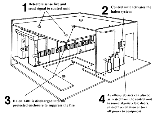
Sketch courtesy Ansul Fire Protection
General Field Decommissioning Procedures
Decommissioning should only be undertaken by qualified fire suppression system service company personnel. Fire suppression system equipment varies according to manufacturer, therefore, it is important to follow the instructions and procedures provided in the manufacturer's manuals. The following provides a discussion of the general procedures involved in removing halon cylinders from a field or on-site location and transporting them to another location, perhaps a reclamation workshop. These steps, in the order in which they should be performed, include (1) securing the halon storage cylinders, (2) disabling the actuation devices, (3) installing the anti-recoil devices, (4) packing the cylinders for transportation, and (5) receiving the shipped cylinders.
Before any steps are taken to disconnect any piping from a halon cylinder, it must first be firmly secured to an immovable object. If this is not done and the valve becomes damaged, the cylinder could accidentally discharge and become a dangerous projectile. Cylinders connected to installed systems are usually adequately secured to the system pipework or manifold.
Once the cylinder is firmly secured, the first step in decommissioning is to disable the actuation devices so the cylinder cannot accidentally discharge. The actuation device triggers the valve to open. The valves are designed such that when activated, they go from a fully closed to fully open position instantly, and the cylinder will be almost completely emptied within 10 seconds. Once the cylinder valve is open it generally cannot be closed.
The most common types of actuation are outlined in Table 1. In most cases, simply disconnecting the device from it's electrical or pneumatic source is not sufficient to deactivate the device. In many cases, it is necessary to remove all actuation devices from the cylinder valves prior to removing the cylinder from the system. Failure to do this, or improper procedures in attempting to remove the actuator, could result in accidental discharge manner that could cause serious injury and death. Most valves are provided with a protective cap to be installed in place of the actuator.
Once the cylinder is firmly secured and the actuation device is disabled, it is safe to carefully disconnect any discharge piping from the discharge port. Immediately upon disconnection of the piping, an anti-recoil device or cylinder protection cap must be installed. The anti-recoil device prevents the cylinder from becoming a projectile in the event the cylinder activates or if the valve becomes damaged. A protection cap is also a device to prevent recoil. It is simply a cap which is secured over the discharge port to prevent the halon from discharging and the cylinder from becoming a projectile. It is important that only the caps designed and manufactured for the specific model of valve be used because the threads are not standardized. If the wrong size is used it may not hold the pressure of the halon release. Anti-recoil device safety caps or plugs must always be properly installed before handling the cylinders.
Most fire suppression system cylinders are furnished with valve outlet anti-recoil devices, and in some cases, cylinder protection caps. DO NOT disconnect cylinders from the piping system, or move, or ship the cylinders if the anti-recoil devices or protection caps are missing. Obtain these parts from an Authorized Distributor or the Manufacturer. These devices are provided for safety reasons and must be installed at all times, except when the cylinders are connected to the piping system or being filled. Fire suppression system equipment varies according to manufacturer, therefore, it is important to follow the instructions and procedures provided in the manufacturer's manuals.
Packing Cylinders for Shipment
Complying with the above safety practices is imperative before removing any cylinders from the mounting position. Once the safety devices are in place, cylinders may be moved with relative safety. However, it is always important to remember that these are high pressure compressed gas cylinders and must be handled according to all the safety procedures applicable to any other high pressure gas cylinder. In addition, proper lifting and transportation practices should be followed. At this point, with the actuating mechanism removed or disabled and the anti-recoil device correctly installed, the cylinder may be moved to the location where the halon will be removed. Sometimes, the halon is removed on site, but usually the cylinders are packaged onto pallets and shipped to a central reclamation point.
****Make certain a now fire protection system is functional after the halon system has been removed and/or notify authority that system is disabled****
At the receiving point for the cylinders, there are a number of safety procedures that must be followed. When opening the shipping container, a halon leak detector or "halon sniffer" should be used to determine if there has been an accidental discharge during transit. If halon is detected, personnel should stay clear of the containers in order to allow any high concentrations of halon to dissipate.
Unloading personnel should then carefully inspect each cylinder to determine which of the following devices is present: (1) burst disk/initiator; (2) mechanical/cutter valve; and (3) Pneumatic actuators and valve core (Shrader valves).
Burst Disk/Initiator
If the burst disk/initiator valve is present, look for initiators and safety caps. If there is no initiator present and the safety cap is in place, the cylinder may be safely unloaded and stored.
If the initiator and safety cap are both in place, the cylinder may be carefully unloaded, but the initiator must be disabled immediately by a qualified technician. It is important not to discharge any static electricity to the initiator or the initiator wiring during unloading. This could cause the valve to discharge. If the initiator is in place and there is no safety cap in place, first connect an electrical ground strap to the cylinder, the vehicle the containers were shipped in, and the person unloading the cylinder. Then install a safety plug or plate over the outlet, taking care not to release any static electricity to the initiator or its wiring. After the anti-recoil device is installed, the initiator must be immediately disabled by a qualified technician.
Mechanical/cutter valve
If the valve is of the mechanical/ cutter type, look for the safety caps and proceed as follows:
If the cutter mechanism is removed and the safety cap is in place, or if the cutter mechanism is in place with a safety cap in it, the cylinder may be safely unloaded and stored.
If the cutter mechanism is in place and no safety plug is installed, DO NOT INSTALL A SAFETY PLUG. Make sure the cylinder is secured to a pallet, and very carefully remove the pallet. Cutter valves are activated by a sharp edge which cuts into the disk sealing the cylinder opening. Be careful that the cylinder and pallet are not dropped or hit hard against anything as this could cause the cutting edge of the mechanism to cut into the disk and discharge the cylinder.
Pneumatic actuation and valve core (Shrader valves)
Pneumatic actuators should be retained on the halon cylinder valve to protect the Shrader valve, especially if an actuation port cap is not available. If the valve type has a Shrader core, look for safety caps and proceed according to the following steps. If safety caps are installed and the release valve or mechanism is secured, the cylinder may be safely unloaded and stored. If the safety cap is not in place and the release mechanism is not secured, install the appropriate safety caps and secure the release mechanism before unloading the cylinder.
General Halon Removal Procedures
Once the halon cylinder has been removed from service, DO NOT VENT OR EMIT THE HALON TO THE ATMOSPHERE. Halon 1301 is necessary for critical uses and can only be derived from existing halon supplies. Therefore, the halon being removed from existing facilities and installations is of great importance and must be conserved.
The procedures for removing halon from cylinders differ depending on the cylinder/valve configuration. Appendix A contains information provided by the various manufacturers of halon system hardware about different types of valves actuation devices, and cylinders. Anyone intending to decommission a system must follow the manufacturers' procedures and guidelines. This must be done before attempting to move cylinders from their current location or remove the halon from the cylinder.
FSSA Safety Alert (October 28, 1993)
 |
SAFETY ALERT |
October 28, 1993 |
DANGER!!
PRESSURIZED (CHARGED) FIRE SUPPRESSION SYSTEM CYLINDERS ARE EXTREMELY HAZARDOUS AND IF NOT HANDLED PROPERLY ARE CAPABLE OF VIOLENT DISCHARGE. THIS CAN RESULT IN SEVERE PERSONAL INJURY, LOSS OF LIFE, AND PROPERTY DAMAGE
The Fire Suppression Systems Association has received reports of several incidents involving charged fire suppression system cylinders that accidentally discharged in an uncontrolled manner when the cylinders were being removed from service or during handling.
IN ALL OF THE INCIDENTS REPORTED TO FSSA THE CAUSE OF THE ACCIDENTS WERE ATTRIBUTABLE TO IMPROPER HANDLING OF THE CYLINDERS BY UNTRAINED AND UNQUALIFIED PERSONNEL. IN ALL CASES, ACTUATING DEVICES HAD NOT BEEN REMOVED FROM THE VALVES AND ANTI-RECOIL DEVICES AND PROTECTION CAPS WERE NOT INSTALLED PRIOR TO REMOVAL OF THE CYLINDERS FROM SERVICE.
These unsafe practices pose a threat to life and property. In the interest of public safety FSSA recommends that the following guidelines be followed:
SAFETY IS OF PRIME CONCERN !
Don't get careless! Never assume that a cylinder is empty. Treat all cylinders as if they are fully charged.
Most fire suppression system cylinders are equipped with high flow rate valves that are capable of producing high discharge thrusts out of the valve outlet if not handled properly.
Remember pressurized cylinders are extremely hazardous. Failure to follow the equipment manufacturer's instructions and the guidelines contained herein may result in serious bodily injury, death, and property damage.
PLEASE NOTE:
The information contained in this document was obtained from sources believed to be reliable, and is based on technical information and experience currently available from members of the Fire Suppression Systems Association and others. However, the Association or its members, jointly or severally, make no guarantee of the results and assume no liability or responsibility in connection with the information or suggestions herein contained. Moreover, it should not be assumed that every acceptable safety procedure or method, precaution, equipment or device is contained within, or that abnormal or unusual circumstances may not warrant or suggest further requirements or additional procedure.
This document should not be confused with federal, state, provincial, or municipal specifications or regulations, insurance requirements or national safety codes. While the Association recommends reference to or use of this document by government agencies and other, this document is purely voluntary and not binding.
Manufacturer's Valve and Cylinder Information
Table 2 lists the major halon system manufacturers' valve and cylinder configurations. More detailed information is provided in Appendix A.
Table 2. Manufacturers' Valve and Cylinder Configurations
|
Manufacturer |
Valve Type |
System Pressure psi |
Agent Weight, lbs |
Part Number |
Valve Assembly Size, inches |
|
Ansul |
High Flow Valve |
360 |
18,33,54,72,90 |
32602 |
1 |
|
Ansul |
High Flow Valve |
360 |
90,186,340 |
32603 |
2 |
|
Ansul |
High Flow Valve |
360 |
600 |
57980 |
3 |
|
Ansul |
High Flow Valve |
360 |
600 |
76114 (replaces 57980) |
3 |
|
Ansul |
Pressure Differential Valve |
360 |
18, 33, 54, 72, 90, 1, 86 |
26850 |
|
|
Ansul |
Cutter Type |
360 |
18, 54, 72, 90 |
16588 |
|
|
Ansul or Wormald |
US Navy Valves |
600 |
10, 15, 60, 95, 125 |
77654N and others |
1. 1.5 |
|
Chemetron |
Alpha Series - Group 1 |
360 |
|
1-048-0720 V |
|
|
Chemetron |
Alpha Series |
360 |
9 to 15 |
1-048-0819 H |
|
|
Chemetron |
Alpha Series - Group 2 |
360 |
|
1-048-0721 V |
|
|
Chemetron |
Alpha Series |
360 |
16 to 26 |
1-048-0820 H |
|
|
Chemetron |
Alpha Series - Group 3 |
360 |
|
1-048-0722 V |
|
|
Chemetron |
Alpha Series |
360 |
27 to 36 |
1-048-0821 H |
|
|
Chemetron |
Beta Series - Group 1 |
360 |
|
1-048-0723 V |
|
|
Chemetron |
Beta Series |
360 |
55 to 95 |
1-048-0822 H |
|
|
Chemetron |
Beta Series - Group 2 |
360 |
|
1-048-0724 V |
|
|
Chemetron |
Beta Series |
360 |
96 to 167 |
1-048-0823 H |
|
|
Chemetron |
Gamma Series - Group 1 (250SB) |
360 |
153 to 268 |
1-048-0726 |
|
|
Chemetron |
Gamma Series - Group 2 (400B) |
360 |
237 to 415 |
1-048-0583 |
|
|
Chemetron |
Gamma Series - Group 3 (550B) |
360 |
314 to 550 |
1-048-0840 |
|
|
Chemetron |
High Flow-600 |
600 |
|
1-061-0720 |
|
|
Chemetron |
Series 70 |
600 |
|
1-061-0730 |
|
|
Chemetron |
High Flow-360 |
360 |
|
1-061-0934 |
|
Table 2. Manufacturers" Valve and Cylinder Configurations Continued...
|
Manufacturer |
Valve Type |
System Pressure psi |
Agent Weight, lbs |
Part Number |
Valve Assembly Size, inches |
|
Fenwal |
Fill charge for HRD Sphere |
360 |
8 to 201 |
06-116300-001 |
|
|
Fenwal |
Spherical Modular Storage Container |
|
|
|
|
|
Fenwal |
Cylinder Valve (Old Style) |
360 |
|
31-19203X-XXX |
|
|
Kidde |
Series 487 Commercial Valves |
360 |
10 to 125 |
486324 |
1.5 |
|
Kidde |
Series 487 Commercial Valves |
360 |
200 to 350 |
486363 |
2 |
|
Kidde |
Series 487 Commercial Valves |
360 |
600 |
486377 |
2.5 |
|
Kidde |
Obsolete Commercial Valves |
360 |
20, 40, 60, 125, 200, 312, 550 |
896150 |
|
|
Kidde |
Military Application Valve |
360 |
|
149743 |
|
|
Kidde |
US Navy Valve (Old Style) |
600 |
10, 15, 60, 95, 125 |
486143 |
|
|
Kidde |
US Navy Valve (Old Style) |
600 |
10, 15, 60, 95, 125 |
898496 |
|
|
Kidde |
US Navy Valve (Obsolete) |
600 |
20, 40, 60, 95, 125 |
877653 |
|
|
Kidde |
US Navy Valve (Obsolete) |
600 |
20, 40, 60, 95, 125 |
840253 |
|
|
Fike |
See Appendix |
|
|
|
|
|
Ginge Kerr |
See Appendix |
|
|
|
|
|
Pyrotronics |
Series H-8 |
360 |
4 to 8 |
|
|
|
Pyrotronics |
Series H-15 |
360 |
9 to 15 |
|
|
|
Pyrotronics |
Series H-30 |
360 |
20 to 30 |
|
|
|
Pyrotronics |
Series H-60 |
360 |
35 to 60 |
|
|
|
Pyrotronics |
Series H-125 |
360 |
65 to 125 |
|
|
|
Pyrotronics |
Series H-250 |
360 |
130 to 250 |
|
|
|
Pyrotronics |
Series H-350 |
360 |
255 to 350 |
|
|
|
Wormald Int. |
Electric Valve Actuator |
360, 600 |
|
303426 |
|
|
Wormald Int. |
1" NGT |
360, 600 |
|
302936 |
|
|
Wormald Int. |
Multiple Stack Actuator |
360, 600 |
|
303444 |
|
|
Wormald Int. |
Mk I, II, III, IV, V, and High Flow |
|
|
|
|
Note: Many halon valves are not marked with part numbers. Use the manufacturer drawings in the Appendix for identification, if necessary.