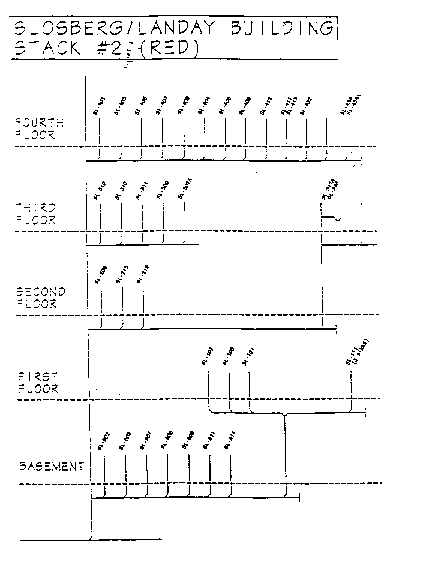
Figure 5.1 Typical "Special Waste" Riser Diagram of Beth Israel Hospital
Source: Beth Israel Hospital, Boston, Facility Engineering Department
The "Special Waste" riser diagrams are an important tool in approaching wastewater compliance for mercury. The riser diagram illustrates to regulating authorities (MWRA) that an institution has extensive knowledge and control of all special waste discharges. The diagram will indicate areas of inability to control and isolate special waste discharges for all "Special Waste" sources. As required by the Massachusetts State Plumbing Code, 248 CMR 2.13 (12/1/93), all plans and specifications for "Special Waste" piping and pretreatment systems shall be prepared by a Registered Professional Engineer.
The inability to contain and isolate the discharge of mercury or other non-compliant wastes into the public sewer system is, in large part, due to the indiscriminate routing of "Special Waste" piping systems, their interconnections with each other, lack of future planning and restrictive economic considerations.
The proposed use of isolation valves in "Special Waste" and vent piping systems under 248 CMR 2.05 (12/1/93), is allowable when the valve would not cause a normal frictional obstruction to flow in the piping system or when the valve has "a desirable and acceptable function and as of the ultimate benefit to the proper and continuing function of the plumbing system." The ability of the isolation valves to allow for trap cleaning, removal of non-compliant wastes, sampling or suspect branch piping and control of waste flow from cross-contaminating the entire special waste piping system would be allowable. However, each proposed installation must have the approval of the local plumbing inspector and each location, when installed with a sampling port, must be approved by the MWRA or the DEP.
The Infrastructure Committee recommends that the following guidelines be followed when planning to install or modify an existing piping system capable of having isolated trap and pipe cleaning procedures:
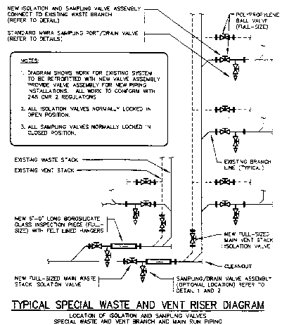
An on-site audit of existing piping systems should be conducted and drawings prepared to reflect the actual waste, vent, and associated pretreatment system installations. Figure 5.1 is an example of a "Special Waste" riser diagram prepared by Beth Israel Hospital. This diagram illustrates individual floors and sinks, with each individual sink identification number, and stack color code and numbering system. An exploded view of a typical "Special Waste" and vent riser diagram is shown in figure 5.2. This diagram displays strategically located isolation ball valves, glass inspection pieces, and sampling/drain valves.
System designs or modifications to an existing system in order to allow isolation of wastes for cleaning, testing, etc., must take into account:
1. The type of wastes being discharged and the piping material compatibility.
2. The future use of laboratory spaces (i.e., chemical changing to blood lab).
3. The need to isolate branch piping from waste and vent stacks to allow piping cleaning without the potential of constricting waste flows from other areas or causing overflows to other uncontaminated piping systems.
4. Caution should be taken when combining any unidentified "Special Waste" piping to previously identified "Special Waste" systems. All waste sources and piping should be investigated for biomass and mercury content prior to combining with previously identified piping. Pending the results of investigation of these new sources, additional isolation valving and/or new dedicated risers to the neutralization system may need to be installed.
The location of isolation valves for cleaning or flow control must be placed with consideration for accessibility and maintenance especially when co-fitted with a sampling port for testing. An example of suggested isolation valve locations is shown in figure 5.2. The location of valves cannot cause an overflow of non-compliant wastes into another area where a spill may occur. As an example, a floor drain would overflow if too much sanitizing liquid used for the pipe cleaning procedure was poured into a countertop sink situated at a higher elevation. Additionally, the need to provide isolation valves in the venting system must not be overlooked for the same reasons.
The sampling port may act as not only a testing point, but also a drain leg for the isolated sanitizing and cleaning agents used in the affected branch of piping. The serrated nozzle may be replaced with a full-size drain leg for the transfer of suspected non-compliant wastes to a container for off-site disposal. See Figure 5.2 for typical locations of sampling/drain valves.

Figure 5.1 Typical "Special Waste" Riser Diagram
of Beth Israel Hospital
Source: Beth Israel Hospital, Boston, Facility Engineering Department

Figure 5.2 Typical "Special Waste" and Venting Riser
Diagram
Source: Flow Tech Associates, Inc., Detail 1B
Vertical "Special Waste" and vent piping risers may need to be isolated in order to allow for sequential cleaning, sanitizing and testing of portions of entire systems in the same manner as has been explained for horizontal runs of piping. During these periods, special consideration must be given to the isolation of vent piping due to the potential for overflow of reagents back through the piping system.
A section of clear borosilicate glass piping should be installed within the main horizontal run of the "Special Waste" conveyance system employing thermo-plastic piping so that flow conditions can be viewed and the formation of biomass accumulation can be periodically observed. Figure 5.2 presents a suggested location for this glass inspection piece. If branch piping containing undiluted hydrofluoric acids is being used, however, this piping should be routed separately and connected downstream of the glass piping and fitted with its own isolation valve and sampling port assembly.
The type of sanitant and cleaning agent being used must be analyzed in conjunction with what may be contained in the piping system from a chemical interaction perspective.
The potential for incompatible reactions should be considered to ensure that trap and pipe cleaning procedures will not create an unsafe condition. Reactions that may cause fuming and result in gas generation into the working environment, as well as into the piping system, must be avoided.
All proposed special waste piping and pretreatment installations, modifications, revisions and additions must be detailed in engineering drawings and specifications certified for 248 CMR 2.0 (12/3/93) compliance (unless otherwise noted as an alternate design) and must be submitted to the local Plumbing Inspector for review and approval prior to construction. These approved documents are then submitted to the jurisdictional authority having control (either the MWRA or the DEP) with the proper permitting documents and supporting engineering design data for final approval prior to discharging wastes to the sewer system.
| Previous | Contents | Next |