|

|
To Print Use The pdf File
ILLINOIS URBAN MANUAL
PRACTICE STANDARD
STRAW BALE BARRIER
(feet)
CODE 935
 (Source: IN Handbook for Erosion Control on Developing Areas) |
DEFINITION
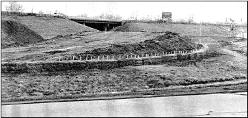
A temporary barrier consisting of a row of entrenched and anchored straw bales or similar material used to intercept sediment-laden runoff from small drainage areas of disturbed soil.
PURPOSE
The purpose of this practice is to cause deposition of transported sediment load from sheet flow leaving disturbed areas.
CONDITIONS WHERE PRACTICE APPLIES
A straw bale barrier may be used subject to the following conditions:
| Slope (%) | Maximum Spacing (ft.) |
|---|---|
| 25 | 25 |
| 20 | 50 |
| 15 | 75 |
| 10 | 100 |
| Flatter than 10 | 125 |
CRITERIA
Straw bale barriers do not require any formal design but the following requirements must be met:
Bales shall be placed in a single row, lengthwise on the contour, with the ends of adjacent bales tightly abutting one another. The end bales should extend upslope so that the trapped sediment laden water cannot flow around the ends of the barrier.
All bales shall be either wire-bound or string tied. Straw bales shall be installed so that bindings are oriented around the sides rather than along the tops and bottoms of the bales in order to prevent deterioration of the bindings. Hay or other baled material may be used in lieu of straw.
The barrier shall be entrenched and backfilled. A trench shall be excavated the width of a bale and the length of the proposed barrier to a minimum depth of 4 inches. After bales are staked and chinked, the excavated soil shall be backfilled and compacted against the barrier. Backfill soil shall conform to the ground level on the downhill side and shall be built up to 4 inches against the uphill side of the barrier.
Each bale shall be securely anchored by at least two stakes (minimum cross sectional area of 3.0 square inches or standard "T" or "U" steel posts (minimum weight of 1.0 pound per linear foot) or rebars driven through the bale. The first stake in each bale shall be driven toward the previously laid bale to force the bales together. Stakes or steel pickets shall be driven a minimum 18-inch deep into the ground to securely anchor the bales.
The holes between bales shall be chinked (filled by wedging) with straw to prevent water from escaping between the bales. Loose straw scattered over the area immediately uphill from a straw bale barrier tends to increase efficiency.
Straw bale barriers shall be installed prior to the clearing of existing vegetation or any site grading.
CONSIDERATIONS
Straw bale barriers should be considered for trapping sediment where sheet and rill erosion is occurring in small drainage areas. Straw bale barriers should not be placed in areas of concentrated flow. The practice standard SILT FENCE 920 does the same job and is usually faster and cheaper to install.
Based on field observations in Illinois and other states, straw barriers have not been as effective as a sediment control measure as they could be. There are four major reasons for this. First, improper use of straw bales has been a major problem. Straw bale barriers have been used in streams and drainageways where high water velocities and/or volumes have destroyed them or significantly impaired their effectiveness. Second, improper placement and installation of the barriers, such as staking the bales directly to the ground with no soil seal or entrenchment has allowed undercutting and flow around the end. This has resulted in additions of, rather than removal of, sediment from runoff waters. Third, inadequate inspection and maintenance lowers the effectiveness of these barriers. Fourth, because straw bales decompose in the presence of moisture, they have a very limited life span.
PLANS AND SPECIFICATIONS
Plans and specifications for installing straw bale barriers shall be in keeping with this standard and shall describe the requirements for applying the practice to achieve its intended purpose. At a minimum include the following items:
Standard drawing IL-635 STRAW BALE BARRIER PLAN may be used as the plan sheet.
OPERATION AND MAINTENANCE
Straw bale barriers shall be inspected immediately after each runoff event and at least daily during prolonged rainfall. Close attention shall be paid to the repair of damaged bales, end runs and undercutting beneath bales.
Necessary repairs to the barrier or replacement of bales shall be accomplished promptly.
Sediment deposits should be removed after each rainfall. They must be removed when the level of deposition reaches approximately one-half the height of the barrier.
Any sediment deposits remaining in place after the straw bale barrier is no longer required shall be dressed to conform to the existing grade, prepared and seeded.
Straw bale barriers shall be removed when they have served their usefulness, but not before the upslope areas have been permanently stabilized.
NRCS IL February 1994