
|
|
|
To Print Use The pdf File
ILLINOIS URBAN MANUAL
PRACTICE STANDARD
INFILTRATION TRENCH
(feet)
CODE 847
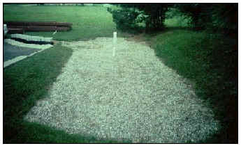 (Source: Center for Watershed Protection) |
DEFINITION
An excavated trench filled with coarse granular material in which stormwater runoff is collected for temporary storage and infiltration.
PURPOSE
The purposes of this practice are to reduce runoff volume and peak discharges from a site, increase groundwater recharge and base flow, and to filter soluble contaminants out of runoff before it reaches receiving waters. Infiltration trenches are not intended to remove coarse sediments.
CONDITIONS WHERE PRACTICE APPLIES
This permanent site development practice applies to small drainage areas not exceeding 5 acres.
The soils surrounding the trench shall have permeability rates of 0.5 to 2.41 in/hr, a minimum available water capacity of 0.15 in/in, and clay content less than 35%. These values can be found in published soil surveys.
Because infiltration trenches are not designed to filter coarse particulate matter, appropriate sediment control devices must be included in the site design and must be installed prior to the construction of the trench.
CRITERIA
Design capacity shall be a minimum volume of 0.5 inches of runoff per acre of drainage area.
The capacity of the trench shall be based on the porosity (% voids) of the coarse aggregate used in the system. If test data is not available, use 40% porosity for the coarse aggregate.
The trench shall be filled with coarse aggregate which meets IDOT CA-1, or CA-3 gradation. The bottom 6 inch layer in the trench shall be sand which meets IDOT CA-14, CA-15 or CA-16 gradation. The coarse aggregate shall be separated from the soil surrounding the trench by a filter fabric. The fabric shall meet the requirements in material specification 592 GEOTEXTILE Table 1 or 2, Class 1 with an apparent opening size of at least 30 for non-woven and 50 for woven. The fabric shall extend through the coarse aggregate one foot below the trench surface to prevent plugging. The filter fabric may be extended across the trench bottom in place of the sand layer.
Infiltration trenches shall be designed to dewater within 72 hours. Table 1 lists the maximum trench depths allowed for various soil types for 48 and 72 hour dewatering time periods. The permeability rate shall be field verified to a depth 3 feet below the trench bottom.
The width of the infiltration trench is determined using the design volume and final trench depth values.
All infiltration trenches must have an overflow component since they are not designed to handle large runoff volumes.
The location of the infiltration trench shall meet the following requirements. The bottom of the trench shall be a minimum of 3 feet above the seasonal high water table, bedrock, an impermeable soil layer or dissimilar soil layer. The trench shall be a minimum of 20 feet downslope or 100 feet upslope from any building foundation. The trench shall be a minimum of 100 feet from drinking water wells, septic tanks, drainfields etc. The trench shall not be installed on landslopes greater than 15% and shall be at least 50 feet from where landslopes are greater than 15%. The trench shall not be installed in fill soils.
Observation wells shall be included with the infiltration trench to enable inspection of their performance. Observation wells shall be constructed of 6-8 inch diameter perforated pipe embedded vertically through the aggregate and extended above the ground surface. The surface protrusion shall be capped and protected against vandalism. A well anchor shall be secured to the pipe to prevent the well from being pulled out of the trench. The well anchor may consist of a metal plate or bar secured at or near the bottom of the observation well.
CONSIDERATIONS
It is absolutely critical that settleable particles and floatable organic materials be removed from runoff water before it enters the infiltration trench. The trench will clog and become nonfunctional if excessive particulate matter is allowed to enter the trench. Runoff filtering practices such as practice standard FILTER STRIP 835, and GRASSED LINED CHANNEL 840 must be installed upstream of the trench. If there are uncontrolled sources of grease or oil, grease traps also need to be installed upstream of the trench.
For the same reasons, control of construction site sediment is critical during trench installation. Appropriate sediment control practices such as practice standards TEMPORARY SEDIMENT TRAP 960 and SILT FENCE 920 must be installed and maintained during construction. A more reliable alternative is to wait to install the trench until construction is complete and the upstream drainage area is stabilized.
Infiltration trenches should not be installed if there is not a reliable long term commitment to upstream sediment control.
Care must be taken to prevent groundwater contamination by not installing infiltration trenches in highly permeable sand or gravel seams that are directly connected to underlying aquifers.
For removal of soluble contaminants, a 12 inch soil layer with a cation exchange capacity (CEC) of 0.5 millieq/100g or greater needs to be present. In Illinois, most soils that meet the permeability, available water capacity and clay content criteria will have a CEC of 0.5 millieq/100g or greater.
PLANS AND SPECIFICATIONS
Plans and specifications for installing infiltration trenches shall be in keeping with this standard and shall describe the requirements for applying the practice to achieve its intended purpose. At a minimum include the following items:
1. System location
2. Depth, width and length
3. Aggregate gradation
4. Filter fabric requirements
5. Observation well details
6. Identification of upstream sediment control BMPs
All plans shall include installation, inspection, and maintenance schedules with the responsible party identified.
Standard drawing INFILTRATION TRENCH IL-547 may be used as the plan sheet.
OPERATION AND MAINTENANCE
During the first year after construction, the observation well should be inspected after each significant rainfall event to ensure that the trench is draining properly. Thereafter, the well should be inspected seasonally.
If the trench clogs, it may be necessary to remove and replace all or part of the filter fabric and possibly the coarse aggregate. The frequency of such repairs will depend on the adequacy of pre-treatment as discussed previously.
Most of the maintenance should be concentrated on the pretreatment practices, such as filter strips and swales, upstream of the trench to ensure that sediment does not reach the infiltration trench.
Maintenance needs are to be discussed with the landowner or operator who is responsible for maintaining the practice.
REFERENCES
Illinois Department of Transportation, 1997. Standard Specifications for Road and Bridge Construction. IL
Ohio Department of Natural Resources, Division of Soil and Water Conservation, 1996. Rainwater and Land Development. 2nd ed., OH
NRCS IL January 1999
|
Maximum Depth for Trenches and Basins Limited by Soil Permeability Rate |
|||
|---|---|---|---|
|
Soil Texture |
Minimum Permeability(fc) in/hr |
Maximum Depth of |
|
|
48 hours (T) |
72 hours (T) |
||
|
Sand |
13 |
NA |
NA |
|
Loamy Sand |
6 |
NA |
NA |
|
Sandy Loam |
2 |
240 |
360 |
|
Loam |
1 |
120 |
180 |
|
Silt Loam |
1 |
120 |
180 |
|
Sandy Clay Loam |
1 |
120 |
180 |
|
Clay Loam <35% Clay |
0.8 |
96 |
144 |
|
Clay Loam >35% Clay |
0.4 |
NA |
NA |
|
Silty Clay Loam <35% Clay |
0.8 |
96 |
144 |
|
Silty Clay Loam >35% Clay |
0.4 |
NA |
NA |
|
Sandy Clay <40% Clay |
0.4 |
NA |
NA |
|
Sandy Clay >40% Clay |
<0.06 |
NA |
NA |
|
Silty Clay |
<0.06 |
NA |
NA |
|
Clay |
<0.06 |
NA |
NA |
NA � not applicable Values based on a Soil Porosity of 40 %.
Maximum allowable depth computed by:
d = (fc)(T)100 / P
where:
d = depth inch
fc = permeability rate inch/hour
T = time to dewater hour
P = porosity (% voids) %
Design Volume of Trench = Required Runoff Volume / Porosity
Porosity = Volume of Voids / Total Volume
Required Runoff Volume = Volume of Voids in Trench