| Overview: |
Fuel cells generate electricity through an electrochemical process in which the energy stored in a fuel is converted directly into direct current (DC) electricity. Because electrical energy is generated without combusting fuel, fuel cells are extremely attractive from an environmental standpoint.
All fuel cells have the same basic operating principle. A fuel
cell is a device that converts the energy of a fuel [hydrogen (H2), natural
gas, methanol, gasoline, etc.] and an oxidant (air or oxygen) into useable
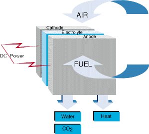
electricity. Fuel cell construction generally consists of a fuel electrode (anode) and an oxidant electrode (cathode) separated by an ion conducting membrane. The input fuel passes over the anode (and oxygen over the cathode)
where it splits into ions and electrons. The electrons pass through an external circuit to serve an electric load while the ions move through the electrolyte toward the oppositely charged electrode. At the electrode, ions combine to create by-products, primarily water and carbon dioxide. Depending on the input fuel and electrolyte, different chemical reactions will occur.
The four primary types of fuel cells (their names correspond to the electrolyte employed) are phosphoric acid, molten carbonate, solid oxide, and proton exchange membrane. A comparison of the fuel cell types is summarized in the table below:
Table 1. Fuel Cell Types Comparison
| PAFC | MCFC | SOFC | PEMFC | | ELECTROLYTE | Phosphoric Acid | Lithium and Potassium Carbonates | Solid-State Ceramic | Polymer Membrane | | OPERATING TEMPERATURE | 375°F
(190°C) | 1200°F
(650°C) | 1830°F
(1000°C) | 175°F
(80°C) | | FUELS | H2 Reformate | H2/CO/Reformate/Natural Gas | H2/CO2/CH4Reformate | H2/Reformate | | REFORMING | External | External/Internal | External/Internal | External | | OXIDANT | O2/Air | CO2/O2/Air | O2/Air | O2/Air | | EFFICIENCY (HHV) | 40-50% | 50-60% | 45-65% | 35-40% |
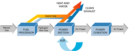
Fuel cells are typically grouped into three sections:
1. Fuel Processor
2. Power Section (fuel cell stack)
3. Power Conditioner
In the fuel processor, a fuel such as natural gas is reformed to chemically extract the hydrogen atom from the host fuel. The hydrogen-rich fuel and oxygen (air) then feeds into the power section to produce DC electricity and reusable heat. This section includes a fuel cell stack, which is a series of
electrode plates interconnected to produce a set quantity of electrical
power. The output DC electricity is converted to alternating current electricity in the power conditioner.
Fuel cells can be configured to provide back-up electrical power should the utility grid experience a power outage. Thermal output from the fuel cell can be used for heating boiler makeup water, space heating, condensate return, process hot water, etc.
|
| Compliance Benefit: |
Because combustion-related
emissions associated with traditional electricity generation are not present
when using fuel cells, the ability of a facility to meet the emissions limits
of an air permit issued in accordance with 40 CFR 70 and 71, or related
state requirements, is increased.
Using alternative or renewable energy sources, such as fuel cells,
will also help facilities meet the requirements under Executive Order 13123,
Greening the Government Through Efficient Energy Management, requiring
facilities leased or owned by the Federal government to be designed and
constructed in a manner that promotes sustainability and minimizes the life-cycle
cost of the facility by using energy efficiency, water conservation, and
renewable energy technologies.
In addition, using alternative or renewable energy sources helps facilities comply
with Title 10 CFR Part 435, "Energy Conservation Voluntary Performance
Standards For New Buildings; Mandatory For Federal Buildings." This Department
of Energy regulation applies to all new buildings and multi-family, high-rise
buildings. These performance standards are designed to achieve the maximum
practicable improvements in energy efficiency and increases in the use of
non-depletable sources of energy.
Using alternative or renewable energy sources helps facilities comply with
U. S. Energy Policy Act of 1992 (EPACT). This legislation was signed into
law on Oct. 24, 1992, and is a comprehensive energy bill covering many areas,
including energy efficiency, fossil fuels, alternative fuels, and federal agency
energy management.
Finally, using alternative or renewable energy sources helps facilities to comply
with the Department of Navyís Naval Facilities Engineering Command Planning And
Design Policy Statement - 98-01: Design of Sustainable Facilities and Infrastructure,
June 18, 1998, which requires all facilities and infrastructure-related design and
construction to incorporate sustainable design principles. This policy includes domestic
construction for the Navy, Air Force (when Navy is the design agent on the project),
and Marines, along with about half of domestic Army construction and about half of
all offshore military construction.
The compliance benefits listed here should be used as general guidelines and should NOT
be strictly interpreted. Actual compliance benefits will vary depending on the factors
involved, e.g., the amount of workload involved.
|
| Materials Compatibility:
|
No materials compatibility issues were identified.
|
| Safety and Health: |
Caution must be exercised with the equipment, as high voltages are a potential danger. Since the process uses combustible materials, proper personal protective equipment must be worn and other safety practices must be employed. Consult your local industrial health specialist and your local health and safety personnel prior to implementing this technology.
|
| Benefits: |
- Improvements in energy conservation and reduced environmental impacts in comparison to traditional energy sources
- High energy conversion efficiency
- Modular design
- Very low chemical and acoustical pollution
- Fuel flexibility
- Cogeneration capability
- Rapid load response
|
| Disadvantages: |
- Initial equipment costs may be high, but are improving as the technology becomes more widely disseminated.
- As with any new and advanced power technology, fuel cells involve design and construction planning as well as additional maintenance training.
- Distributed power sources require dedicated on-site space requirements.
- Caution must be exercised since high voltages are a potential danger.
|
| Economic Analysis: |
The National Defense Center for Environmental Excellence (NDCEE), which is operated by Concurrent Technologies Corporation, was tasked by the U.S. Army Construction Engineering Research Laboratory (USACERL) to design and construct a national resource for the independent, unbiased testing and validation of fuel cell power plants for military and commercial applications. The purpose of this task was to provide testing and evaluation of an UTC Fuel Cells 200 kilowatt (kW) PC25C Phosphoric Acid Fuel Cell Power Plant to achieve life-cycle cost reduction and performance improvements. (Note: UTC is not planning on manufacturing its PC25C PAFC. It is moving forward with a PC35 PEMFC.)
As part of this task, the NDCEE determined that the average cost for a typical installation excluding any geographic cost index adjustments for labor should be in the $90,000 to $100,000 range. Any non-typical or auxiliary equipment will be in addition to the base installation cost.
The installation costs for some of the military fleet have been recorded and tabulated to allow review of installation options, interface requirements, and installation cost. These initial fuel cell systems cost an average of $110,109, with a minimum cost of $83,729 and a maximum cost of $199,388.
A typical PC25C installation will include the following basic components. This list is for a typical outside installation using the standard heat recovery capability.
- Concrete pad for the fuel cell, designed for the structural weight of the system and site geological requirements
- Concrete pad for the air cooling module, if located separately from the fuel cell
- Six feet high chain link security fence surrounding the fuel cell and cooling module
- System water piping connections, supply and drain
- Nitrogen gas system for purge requirements
- One data and one voice telephone line
- Electrical interconnection to grid
- Heat recovery thermal interface
- Standard instrumentation
Non-typical items associated with PC25C installations may be as follows. These items are site specific and will require input from engineering and operation personnel at the specific site.
- Thermal storage equipment, for the possibility of increased utilization of the available thermal output
- High voltage requirements, if the fuel cell system is to be connected directly to a high voltage electrical system
- Electrical interconnection to the grid independent electrical loads
- Extended or lengthy electrical and thermal connection interfaces (long interfaces increase installation costs)
- Special piping material needs, site-specific requirements
- Special thermal equipment (absorption chilling equipment to supplement a continuous cooling need)
- Dual-fuel input capabilities
- Complex site conditions and utilities interference
- Indoor installations, a ventilation system is a requirement for indoor installations
A typical fuel cell installation would involve a flat site with minimal site preparation required. An existing concrete pad in close proximity to the electrical and thermal source would create an ideal site for the equipment placement. For a typical PC25C installation, the required length to reach an appropriate electrical interconnection and the thermal interface should be 100 feet or less.
|
| NSN/MSDS: |
None identified.
|
| Approving Authority: |
Appropriate authority for making process changes should always be sought and obtained prior to procuring or implementing any of the technology identified herein.
|
| Points of Contact: |
For more information
|
| Vendors: |
USACERL was assigned the mission of managing the Fuel Cell Demonstration Program for the DoD. USACERLís specific tasks include developing turnkey fuel cell packages, devising site selection criteria, screening DoD candidate installation sites against selection criteria, evaluating viable applications at each candidate site, coordinating fuel cell site designs, installation and acceptance of the fuel cell power plants, and performance monitoring and reporting. The DoD Fuel Cell Demonstration Program sites represent a broad spectrum of facilities and locations throughout the major Services.
This is not meant to be a complete list, as there may be other manufacturers of this type of equipment.
UTC Fuel Cells
195 Governorís Highway
South Windsor, CT 06074
Phone: (866) FUELCELLS [(866) 383-5235]
FAX: (860) 727-2319
Email: UTC Fuel Cells General Inquiries
URL: www.utcfuelcells.com/index.shtml
FuelCell Energy, Inc.
Corporate Headquarters
3 Great Pasture Road
Danbury, CT 06813-1305
Phone: 203-825-6000
Email: sales@fce.com
URL: www.fuelcellenergy.com
Plug Power
General Inquiries
968 Albany-Shaker Road
Latham, NY 12110
Phone: (518) 782-7700
FAX: (518) 782-9060
URL: www.plugpower.com
Siemens/Westinghouse Power Corporation
Science and Technology Center
Fuel Cells Division
1310 Beulah Road
Pittsburgh, PA 15235-5098
URL: www.siemenswestinghouse.com
|
|
| Related Links: |
None.
|
| Sources: |
Mr. Scott Kenner and Mr. Bob Unger, Concurrent Technologies Corporation, February 2003.
US Army Corps of Engineers, Construction Engineering Research Laboratories (CERL). DOD Fuel Cell Demonstration Program. http://www.dodfuelcell.com/ Accessed June 12, 2001.
Concurrent Technologies Corporation. U.S. Army Engineering Research and Development Center (ERDC) Construction Engineering Research Laboratories (CERL) Fuel Cell Program Final Report. Johnstown, PA. December 28, 2000.
|
| Supplemental: |
Figure 1. Schematic of the operating principal of a fuel cell 
Figure 2. Sections of a fuel cell 
|


