|
Controlled Spraying and Laser Touch®
in the Fiber Reinforced Plastics Industry
Controlled spraying significantly reduces
styrene emissions from open mold fiber reinforced plastic
application processes. This pollution prevention technique
benefits plant personnel, the manufacturing operation and
natural environment, by increasing material transfer efficiency,
which reduces styrene emissions.
Transfer efficiency is the amount of material
hitting the mold compared to the amount of material sprayed.
Increase transfer efficiency in your FRP shop by minimizing
resin atomization and reducing overspray loss—material
that misses the mold during spray application. Both atomization
and overspray expose the surface area of resin and gelcoat
particles to air, increasing styrene emissions.
| A study by the Indiana
Clean Manufacturing Technology and Safe Materials Institute,
Purdue University, showed that styrene emissions from
gelcoat and resin application could be reduced by 20 percent
or more through controlled spraying. Composites Fabricators
Association (CFA) tests show that styrene emissions are
directly related to the exposed surface area and are independent
of the film/layer's thickness. According to CFA's Controlled
Spraying Handbook, three major elements work together
to reduce emissions: |
| • |
Spray gun settings |
| • |
Capturing overspray at
the mold perimeter |
| • |
Training operators |
Spray Gun Settings
Spray guns transfer resin or gelcoat from bulk containers
to the mold. Sprayed in a fan shaped pattern material efficiently
covers the mold. In the case of externally mixed spray equipment—mixing
catalyst and resin after they exit the spray gun—the
finely divided liquid droplets of the fan pattern aid in mixing
the catalyst with the resin or gelcoat. Proper mixing is required
to adequately cure the laminate.
Calibrate Pressure
The amount of atomization depends on a variety of characteristics,
including resin temperature and properties, type of spray
gun, gun-to-mold spray distance and mold shape. Each set of
characteristics has an acceptable amount of atomization. To
minimize atomization use the lowest gun fluid tip-pressure
that gives an effective fan pattern and insures adequate mixing
of the catalyst and resin or gelcoat. Maintain a pressure
calibration log so you can track if operators are monitoring
atomization. More details are available on CFA's
Web site and in chapter 4 of the Controlled
Spraying Handbook.
Control the Fan Pattern
Select a fan pattern that allows operators to work efficiently
while maintaining control over the resin or gelcoat's placement
and thickness. Match orifice size and tip angle to the resin's
characteristics and to the size and shape of the mold. Use
wide spray patterns for wide parts and narrow spray patterns
for narrow parts. Because spray equipment varies, consult
the manufacturer to determine the best operating pressure
for a given set of conditions. In general, as tip pressure
increases the fan pattern moves from a circular pattern to
an erratically elongated pattern to a “clean” elliptical
pattern. At higher pressures, an undesirable larger elliptical
pattern forms. Ideal conditions are usually at the lowest
pressure that yields an elliptical pattern. This distributes
material evenly across the fan, providing uniform coverage.
Capturing
Overspray
To minimize the amount of material that hits the floor,
capture overspray as close to the mold's edge as possible.
This will reduce styrene emissions. Capture overspray
by: |
| • |
Widening the mold's flange |
| • |
Incorporating a removable
flange extension |
| • |
Using wide disposable masking
|
Operator Spray Technique
Spray technique has a significant impact on the amount of
waste generated in open mold processes. Inefficient technique
results in excess material use, reduced transfer efficiency
and increased amounts of overspray. Train operators to maximize
your operation's efficiency.
Thoroughly train operators on proper spray
techniques. Explain the need for controlled spraying, including
how overspray impacts material use and styrene emissions.
Also, explain the importance of proper spray equipment setup
and spray technique.
| Proper
spray techniques |
| 1. |
Spray gun orientation.
Hold the gun perpendicular to the mold surface as material
is applied. A more even mil thickness and the least overspray
is produced the closer the gun's angle is to 90 degrees. |
| 2. |
Spray pattern. Establish
a pattern that gives the proper coverage. Use smooth,
long parallel strokes. Start at the area of the mold closest
to the operator and follow the mold's contour as closely
as possible. Keep the stroke rate, gun-to-part distance
and gun angle constant. |
| 3. |
Mold perimeter. Spray the
mold's perimeter first, keeping overspray within the containment
flange. Next, work from the mold's interior out to the
perimeter, stopping short of the mold's edge. |
| 4. |
Corners. Spray inside and
outside corners at a 45 degree angle. |
| 5. |
Large molds. A large mold
may make it difficult for an operator to keep the gun
angle at 90 degrees near the mold's center. In this case,
add material starting from the outer edge working to the
interior. At the center of the mold deviating the angle
from perpendicular is less of a problem because material
is likely to fall on the mold's surface and not become
overspray. |
| 6. |
Gun operation. Do not trigger
the spray gun on and off. This could make the catalyst
and resin ratio inconsistent. |
| 7. |
Mil thickness monitoring.
Operators should use a mil thickness gauge to monitor
laminate buildup. This check helps ensure that they hit
the target weight for parts and keep overall emissions
minimal. Or, use equipment that monitors the amount of
material dispensed to achieve tighter control over part
weights. |
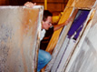
Laser Touch® Improves Spray Technique
and Reduces Waste
Adequate training increases the efficiency
of material use. Spray performance can improve further when
a properly trained spray operator is assisted by Laser Touch®
technology. Mounted on a spray gun, the Laser Touch® unit
has two laser beams that converge into one when the gun is
properly positioned. The visual signal of both lasers coming
together on a part lets operators instantly know if they have
proper aim, gun-to-part distances and gun angle. Improved
accuracy and consistency ensures material placement, maximizing
transfer efficiency. The increased performance is seen as
less waste is produced.
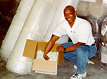
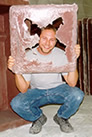
Fiberglas Fabricators
Tests Laser Touch®
A MnTAP intern studied the effectiveness of Laser Touch®
at Fiberglas Fabricators, in Le Center, Minnesota. The company
manufactures electric utility enclosures of varying sizes
and shapes. The parts are rectangular and have a depth of
one foot or more. The base of each part is cut out, creating
a large source of waste. Trim and overspray are the other
major waste sources.
The intern tested Laser Touch® on a
variety of parts in an average day’s production. An initial
waste assessment was performed to set baseline waste numbers.
The amount of gelcoat applied to the mold was determined by
weighing the mold before and after application. Filled resin,
catalyst and chopped glass inputs were monitored by Technology
for Manufacturers® (TFM) material monitoring device. Woven
glass was weighed on a scale. Before the part was allowed
to cure, the waste from the mold edge—trim waste—was
removed and weighed. After the part was removed from the mold,
edge finishing and cut out wastes were weighed. Overspray
waste was the difference between the inputs and the cut out
and trim wastes. Parts were carefully monitored throughout
the process and the same spray operator performed all the
tests. The application equipment used was the Magnum fluid
impingement technology (FIT). Styrene emissions were not included
in the analysis.
Using the CFA’s Controlled Spray Program
as the guide, the operator for this study was trained on proper
spray technique. The Laser Touch® was installed and set
for the desired gun-to-part distance. Materials used and waste
generated were determined as described above.
Data and Results
Tables 1 and 2 represent data for a variety of different parts.
Identical parts are represented in each trial, but direct
comparisons cannot be made between tables. The average waste
rate was 14.5 percent before using Laser Touch® versus
10.6 percent after. The Laser Touch® device and the controlled
spray training resulted in nearly a 27 percent reduction in
the solid waste generated.
| Table 1. Baseline
material use and waste data for a variety of parts in
typical production. |
 |
| Part |
Materials used*
(pounds) |
Waste generated
(pounds) |
Percent waste |
| 1 |
62.8 |
10.7 |
17.0 |
| 2 |
62.5 |
8.6 |
13.8 |
| 3 |
62.2 |
7.45 |
12.0 |
| 4 |
59.8 |
9.1 |
15.2 |
| 5 |
59.35 |
12.65 |
21.3 |
| 6 |
58.8 |
10.9 |
18.5 |
| 7 |
134.4 |
13.4 |
10.0 |
| 8 |
137.1 |
21.5 |
15.7 |
| 9 |
136.5 |
13.5 |
9.9 |
| 10 |
126.1 |
21.1 |
1.7 |
| 11 |
126.6 |
15.6 |
12.3 |
| 12 |
60.55 |
11.2 |
18.5 |
| 13 |
60.15 |
10.3 |
17.1 |
| |
|
|
|
| Total |
1147.0 lbs. |
166.0 lbs. |
Average 14.5% |
|
| *Materials used is total
amount of catalyzed filled resin, gelcoat, chopped and
woven glass that is applied. |
| Table 2. Material
use and waste data for a variety of parts using the Laser
Touch® device. |
|
| Part |
Materials used*
(pounds) |
Waste generated
(pounds) |
Percent waste |
| 1 |
58.85 |
7.0 |
11.9 |
| 2 |
62.7 |
6.9 |
11.0 |
| 3 |
129.4 |
9.9 |
7.7 |
| 4 |
129.9 |
10.6 |
8.2 |
| 5 |
63.9 |
5.6 |
8.8 |
| 6 |
66.15 |
5.0 |
7.6 |
| 7 |
62.7 |
8.5 |
13.6 |
| 8 |
63 |
7.1 |
11.3 |
| 9 |
68.3 |
9.0 |
13.2 |
| 10 |
70.2 |
12.2 |
17.4 |
| |
|
|
|
| Total |
775.0 lbs. |
82.0 lbs. |
Average 10.6% |
|
| *Materials used is total
amount of catalyzed filled resin, gelcoat, chopped and
woven glass that is applied. |
Table 3 represents a before and after comparison
for identical parts. Large and small parts are represented
in the sample. The large part averaged a 22 percent decrease
in waste while smaller parts averaged a 33 percent decrease.
| Table 3. Before
and after Laser Touch® comparisons of waste data for
identical parts. |
|
| Part |
Waste
(pounds per 100 pounds input*) |
Percent
decrease |
| |
Before |
After |
|
| A |
12.9 |
8.8 |
32 |
| B |
11.9 |
7.9 |
34 |
| C |
17.8 |
13.9 |
22 |
|
| *Input equals the sum of
resin, glass, catalyst and gelcoat into part. |
Economics
Because of the quick payback, Fiberglas
Fabricators will consider purchasing Laser Touch® if it
does not move to robotic spray up.
| Table 4. Economic
justification for implementing controlled spray using
the Laser Touch® |
|
| Annual savings
in materials if scrap rate dropped from 14.5 to 10.6 percent |
$23,700 |
| |
|
| Decrease in landfill disposal
costs |
20 percent |
| |
|
|
Savings associated with decreased
landfill costs
|
$2,600 |
| |
|
|
Total annual economic benefit
|
$26,300 |
| |
|
Cost of Laser Touch®
(4 units at $1,000 each, including installation) |
$4,000 |
| |
|
| Payback period |
< 2 months |
|
MnTAP has a variety of technical assistance
services available to help Minnesota Businesses implement
industry-tailored solutions that maximize resource efficiency,
prevent pollution and reduce costs. Our information resources
are available online. Or, call MnTAP at 612/624-1300 or 800/247-0015
from greater Minnesota for personal assistance.
The Laser Touch® study was conducted
in 2001 by Randy Cook,
MnTAP engineer, and MnTAP intern Kevin Sandstrom, a chemical
engineering junior at the University of Minnesota.
|