Waste Treatment Technology in JAPAN
Drying, Incineration and Melting
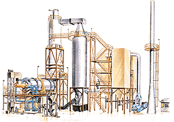
Thousands of types of wastes, including hazardous, toxic, non-hazardous industrial solids and sludges, biomedical, and contaminated soils can be incinerated by Kobe Steel rotary kiln incineration system licensed by ABB Raymond, USA.
The system illustrated below features a current technology configuration. Each system is specifically designed for the particular application.
(l)Waste preparation systems can include liquid/solid separation or shredding of bulk and packaged solid and non-pumpable materials. Shredding reduces waste to a smaller and more uniform size, improving incineration efficiency.
(2)Feed systems can include conveying equipment for packaged and bulk solids, chutes, ram feeders, screw feeders, and shredder/auger feeders for feeding solids and non-pumpable materials. Slurries, aqueous wastes and pumpable sludges are fed through lances. Waste liquids can be fed either through lances or through burners.
(3)Rotary kiln is the heart of the incineration system. The kiln is specifically designed to efficiently incinerate a wide spectrum of wastes. The tumbling action of the rotating cylinder provides continuous exposure of new surface areas of the waste material to the combustion air and hot refractory surface, maximizing organic burnout, converting the organics, water and other portions of the wastes to a gaseous phase, and leading to significant waste volume reduction. The kiln is typically operated at temperatures from 1400 deg.F(760 deg.C) to 2500 deg,F(1370 deg.C). Waste residence time and mixing are varied by changing rotational speed. The kiln is typically operated in an excess air mode, but can be operated substoichiometrically. Oxygen-enriched incineration operation can also be provided.
(4)The secondary Combustion System (SCC) is integrally connected to the rotary kiln through a discharge breeching. The SCC typically provides 1 to 3 seconds gas residence time to complete the combustion of the organics in the flue gases. It also employs excess air (oxygen), high temperature (typically 1800 to 2200 deg.F, 980 to 1200 deg.C) and turbulence to achieve high DRE's (99.99% typically, 99.9999% for TSCA wastes). Liquid wastes may also be fed directly to the SCC.
(5)The bottom ash removal system is located under the discharge breeching. It receive and conveys the ash residue from the kiln and SCC, utilizing dry or wet cooling. A seal is maintained at this point between the incinerator and the surrounding environment.
(6)Gas conditioning cools the gases prior to entering the downstream air pollution control equipment. In the system shown, atomized water is introduced into a spray dryer. Alternatively, this may be done by introducing air.
(7)Air pollution control (APC) systems remove acid gases, particulate matter, dioxins, furans and heavy metals. This can offer in several configurations. Technology employed may consist of wet APC systems (e.g., high-efficiency venturi scrubbers, packed beds, tray towers, wet electrostatic precipitators), dry APC systems (e.g., electrostatic precipitators or bag houses with dry chemical injection), or semi-dry APC systems (e.g., spray dryers or evaporative coolers with electrostatic precipitators or bag houses).
(8)The induced draft fan draws system gases through the entire system, maintaining a negative static pressure throughput.
(9)The stack discharges the flue gases at an elevated level. A sampling platform and test ports can also be provided.
Kobe Steel's incineration systems are available in three basic types: permanent systems for long-term treatment at a specific site, transportable modular systems which allow complete relocation of the entire facility, and mobile systems built on trailers to minimize construction, commissioning, and disassembly time.
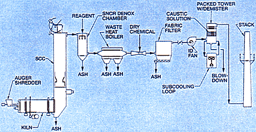
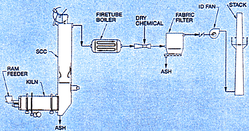
Typical system configurations are shown in Figure 1 and 2.
Figure 1 - Hazardous waste incinerator.
Figure 2 - Biomedical incineration system.
[Application]
[Technology Configuration]

Energy Recovery Systems (not shown) may be used to generate process steam and/or electricity, to pre-heat combustion air or perform other energy-saving tasks.
(10)A continuous emissions monitoring (CEM) system monitors the flue gas for concentrations of gases indicative of incineration performance (e.g., CO, O2, CO2, total hydrocarbons) and to confirm air quality regulatory compliance (e.g., HCl, SOx, NOx, opacity).
[Typical System Types]
[System Configurations]
Figure 1: Hazardous waste incinerator with auger/shredder, selective non-catalytic reduction (SNCR) of NOx, energy recovery, dry chemical injection with bag house dust collector, and wet acid gas packed tower scrubber with sub-cooling of flue gases.
Figure 2: Biomedical incineration system including ram feeder, fire tube boiler and dry lime injection upstream of the bag house dust collector.

