Waste Treatment Technology in JAPAN
Drying, Incineration and Melting
(1-4) Features
-Free from Kinds of Refuse
-Rigid and Clogging Free
-No Clinker Adhesion
(2-1) Rotary Kiln
(2-2) Secondary Combustion Furnace
(2-3) After-Burning Stoker
1. Kawasaki Rotary Kiln+Stoker Furnace System
(1-1) Outline
This system has been developed with a purpose of dissolving the clinker adhesion Problem to the furnace wall and of improving ignition loss, while taking the advantage of good points of the rotary kiln. This system can thus handle mixed incineration of any kind of wastes.
(1-2) Applicable Field
Waste plastics, waste rubbers, oil sludge, inorganic and organic sludge, paint residue, waste oils, waste solvents, waste liquids, waste woods, waste paper, general refuse, etc.
(1-3) Size of Facility
	Capacity :	10 - 200 T/D
	Ignition Loss :	3X or less
A combination of kiln and stoker enables complete combustion of any kinds of refuse. Wide range of applicable scope is the most typical feature, thus accepting any kind of refuse.
The system is provided with a large charging and discharging chutes. Even when foreign materials such as metals are contaminated, they will be discharged without clogging within the furnace. Therefore, they need not be shredded into pieces beforehand.
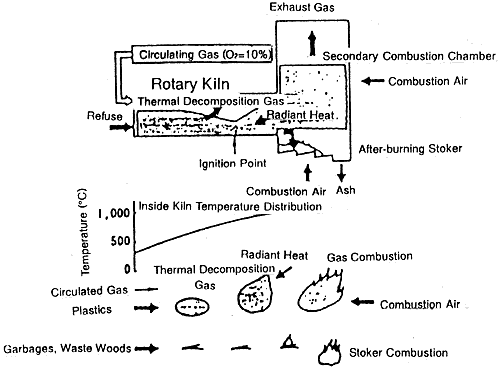
There is no time to allow clinker adhesion since refuse is first combusted at a low temperature, and then sent to stoker for after burning, thus ensuring quick discharging from the kiln.
2. Configuration
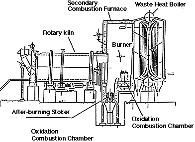
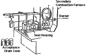
Rotary kiln is a cylinder of steel plate and is provided with a lining of special heat-resistant material, and the entire kiln is slightly inclined towards the outlet. Incineration is carried out while the kiln slowly rotates to stir the refuse and feeds it frontward. The hood at the inlet incorporates the feeder for fixed refuse, starting burner, waste oil burner, slurry nozzle, waste liquid nozzle, etc.
The outlet of rotary kiln is provided with the secondary combustion furnace which is given with a lining of fire-resistant bricks. The secondary combustion furnace is 0 provided with a waste oil burner, a waste liquid nozzle, and an air nozzle for secondary combustion. Air is blown into the furnace at a high speed to stir and mix combustion gas, thus ensuring after-burning.
Ash and unburned refuse that are discharged from the rotary kiln will fall onto the after-burning stoker for complete incineration. Along with the operation of the stoker, ash and unburned refuse will move forward while slipping downward on the stepped area. They will be stirred well while they are falling onto the stoker, and they will be completely burned as they meet the air blown from the bottom of the stoker. It is possible to install a feed hopper or a feed pusher which allows direct charging of refuse into the stoker.
Model Diagram of Suppressed Combustion System


1-1 Higashikawasaki-cho 3 -chome, Chuo-ku Kobe 650-91 Japan
Tel : +81-78-360-8653 Fax : +81-78-360-8661