UNL's
Livestock Environmental Issues Committee
Includes representation from UNL, Nebraska Department
of Environmental Quality, Natural Resources Conservation Service, Natural
Resources Districts, Center for Rural Affairs, Nebraska Cattlemen, USDA
Ag Research Services, and Nebraska Pork Producers Association.
Inside
This Issue:
The different types of manure injectors and incorporators
and their efferct on crop residue
Contact:
Rick Koelsch
218 LW Chase Hall
University of NE
Lincoln, NE 68583
(402) 472-4051
chenry@unl.edu
|
||||||||||||||||||||||||||||
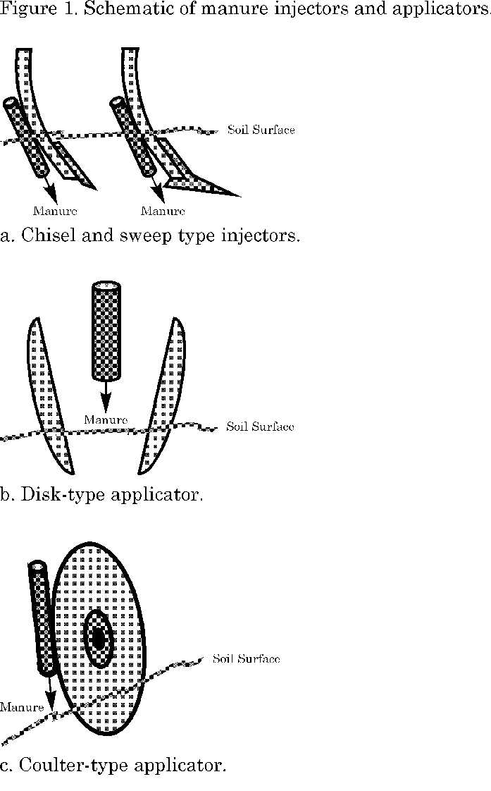
Three general configurations of soil-engaging components are typically used with tank spreaders and towed hose systems to simultaneously apply and incorporate either liquid or slurry manure. These are: Chisels and sweeps (Figure 1-a.) are the most common components for manure application/incorporation. These generally consist of a C-shaped shank, 2-3 inches wide, with either a chisel or sweep point bolted to it. Chisel points are typically 2-3 inches wide, and can be either straight or twisted. Sweeps are typically 7-24 inches wide. At least one manufacturer offers a combination chisel point and sweep as a single unit. Shank spacing on the toolbar usually ranges from 20 to 60 inches. Most manufacturers also offer coulters that can be mounted in front of the shanks to help cut the crop residue, which improves residue flow through the shanks. Operating depth of chisels and sweeps is usually 4-8 inches. Manure exits the supply tube below the soil surface, making these units true manure injectors. Disk-type applicators (Figure 1-b) consist of two opposed concave disks, typically 14-22 inches in diameter, mounted on an angled shaft. Spacing between the centers of the individual disks is generally 12-24 inches. Because of the angled shaft, the disks are skewed to the direction of travel, giving a wider spacing between the disks at the front edges than at the rear. Manure exits slightly above the soil surface through the supply tube between the disks. Operating depth is generally 3-6 inches. As the applicator moves through the field, the disks throw loosened soil and crop residue upward and toward each other, mixing them with the manure flowing from the supply tubes. Following application, the field often appears as strips of essentially undisturbed residue and soil alternated with strips of mixed soil, residue, and manure. The width of the undisturbed strip is dependent on both the spacing between the two opposing disks, and the spacing of the disk units along the toolbar, which is typically 15-60 inches. Coulter-type applicators (Figure 1-c) consist of a large rolling coulter, typically 22-25 inches in diameter, a manure supply tube, and a closing or press wheel. The coulter is slightly skewed or twisted compared to both the direction of travel and to vertical. As the applicator moves through the field, the soil and residue is cut by the coulter, and a slot, where the manure is applied, is wedged open. The press wheel then forces the slot closed. Coulter applicators should be operated in pairs, with one skewed to the right and one skewed to the left, to eliminate implement side-draft. A recent research project at the University of Nebraska Northeast Research and Extension Center near Concord evaluated the influence on residue cover reduction of various configurations of these components (Table 1). Evaluations were made in soybean residue and in both irrigated and non-irrigated corn residue. Trials were conducted in the Spring and Fall of both 1996 and 1997. Table 1. Summary of injection/application equipment used*.
In general, the least amount of residue cover remained when chisel and sweep injectors were used, similar to using a tandem disk (Table 2). More cover remained with the disk-type applicators than with the chisels and sweeps, but not as much as with the coulter-type applicator. Table 2. Percentage of initial residue cover retained.
For planning purposes, the values in Table 2 can be multiplied by the percent residue cover present before manure incorporation to obtain an estimate of the amount of cover that will remain following manure incorporation. For example, assume that a coulter-type applicator will be used to apply manure in a recently-combined soybean field having an average residue cover of 85%. Multiply 85% (after harvest cover) by 0.7 (estimated cover remaining for a coulter-type applicator used in soybean residue) which gives about 60% residue cover following manure application. In contrast, if chisel or sweep injectors were used in the same soybean field, less than 10% cover would likely remain. As with tillage operations, the amount of residue cover remaining after application/incorporation of manure is influenced by many factors including: implement design, adjustments, speed, depth of soil disturbance, previous residue disturbance, and soil and residue condition. Thus, the best procedure is to operate the manure incorporation equipment in a small, representative area of the field, and then measure the amount of residue cover remaining using the line-transect method. (Refer to University of Nebraska Cooperation Extension NebGuide G93-1133-A, "Estimating Percent Residue Cover Using the Line-Transect Method".) Also, manure incorporation is usually only one operation within a series or system of operations that are performed in a field between harvest of one crop and planting of the next crop in that field. Each soil and residue-disturbing operation must be considered when evaluating the amount of residue that will remain for erosion control. (For more information about the influence of various factors on residue cover, as well as a more complete listing of equipment and residue amounts remaining, refer to University of Nebraska Cooperation Extension NebGuide G93-1135-A, "Estimating Percent Residue Cover Using the Calculation Method".) Results of this research project indicate that adequate residue cover can remain for effective erosion control with some configurations of manure injectors/applicators, particularly in corn residue. However, the equipment must be selected, adjusted, and operated with the dual objectives of manure and residue management, rather than the objective of simply disposing of the manure. With this information, livestock producers should be better able to select a manure management system that is also compatible with their soil erosion control objectives. Acknowledgments: Financial support for this project has been provided
by the Nebraska Pork Producers Association and the University of Nebraska
Institute of Agriculture and Natural Resources Agricultural Research Division.
Manure equipment was supplied by Balzer Manufacturing Corp., Mountain Lake,
MN; Calumet Division of Imperial Industries Inc., Wausau, WI; Sukup Manufacturing
Co., Sheffield, IA; and Vittetoe, Inc., Keota, IA.
|
||||||||||||||||||||||||||||
|
|
||||||||||||||||||||||||||||