
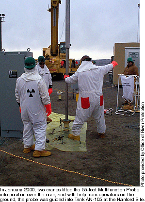
More than 300 million liters of radioactive waste are stored in 280 large radioactive waste storage tanks and seven calcine storage facilities at DOE sites across our nation. Many of these tanks have exceeded their design life and, if left in place without stabilization, represent significant occupational and public risks. Although baseline tank remediation processes are planned or operating, science and technology investments are needed to address the associated high costs, technical risks, and operational inefficiencies. Using an integrated approach that brings together users, technology developers, and producers, the Tanks Focus Area mission is to facilitate the development and delivery of technical solutions that enable tank waste remediation to be successful throughout the DOE complex. Each of the DOE tank sites is at a different stage in its tank remediation efforts. The Oak Ridge Reservation and West Valley Demonstration Project have retrieved the majority of the bulk wastes and are focused on residuals removal and tank closure. The Savannah River Site is continuing sludge and heel retrieval to feed its vitrification facility and to continue tank closure. The Hanford Site has accelerated its single-shell tank interim stabilization efforts and is preparing for waste retrieval to support feed delivery to a private treatment vendor, while the Idaho National Engineering and Environmental Laboratory is focused on interim stabilization for liquid tank waste removal while developing a permanent baseline for site treatment. This article presents highlights of recent TFA technical solutions for the various tank remediation phases. Safe waste storage Electrochemical Noise Corrosion Probe TFA and partners at the Hanford Site worked together to develop and deploy corrosion probes using electrochemical noise (EN) monitoring capability to combat corrosion in double-shell tank walls. The EN technology measures noise generated as a result of electrochemical reactions occurring at corroding surfaces—in this case, on parts of the probe constructed of the same material used to build the original tanks. Development and deployment of a prototype EN corrosion probe was completed in 1996. Two more probes were then designed and deployed in 1997 and 1998, each one enhanced with progressively more complex instrumentation and software. Using integrated data analysis software, the probe notifies operators when corrosion is occurring, allowing them to take quick and effective actions. Based on results from the previous probes installed in Hanford tanks, hardware and controls for the latest upgraded multifunction probe were delivered to tank farm operations in August for deployment into double-shell tank AN-105 in January 2000. In addition to the eight channels of corrosion-monitoring electrodes included on previous probes, the new system is also fitted with 22 thermocouples, a tank waste high-level detector, ports for pressure/gas sampling, and a set of strain gauges to monitor the effects of tank operations on the downhole instrumentation. These new features add greater functionality to the probe, providing a better understanding of the relationship between corrosion and other tank operating parameters and optimizing the use of the tank riser that houses the probe. Waste mobilization and retrieval Gunite Tank Cleaning System
The system began operating in the gunite tanks in 1998 and has completed sludge retrieval in five tanks (W-3, W-4, W-6, W-7, W-10), meeting regulatory requirements for acceptable retrieval levels. The system has since been relocated to another gunite tank (W-8) in preparation for retrieval activities there. Waste conditioning and transfer
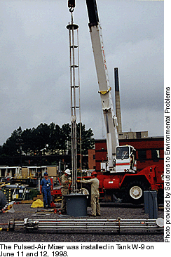
The mixer delivers pulses of compressed air from an array of plates near the bottom of the tank. The resulting air bubbles rise through the waste and pop, creating a vigorous mixing action. This effectively suspends the light waste fraction from the heavier particles, maintaining the lighter portion near the waste surface. This lighter waste can then be safely pumped through waste transfer pipelines. Initial operations of the Pulsed-Air Mixer in Tank W-9 occurred in December 1998 to evaluate the mixer’s compatibility with the gunite tank waste. Waste transfers began in May 1999, with the Pulsed-Air Mixer operating to maintain the solids concentration of the wastes in Tank W-9 between ~3.4 and 3.8 percent prior to transfer. As of January, the system had completed a dozen transfers, with more than 1 million liters of sludge and 40,753 curies safely transferred to the new Melton Valley tanks. Waste pretreatment Crossflow Filtration/Out of Tank Evaporator/Cesium Removal
System A modular solid-liquid separation system using crossflow filtration technology (OST/TMS ID 350) was developed to filter the MVST waste. The system segregates undissolved solids from supernatant, supporting downstream processing operations for both liquids and solids and preventing carryover of radionuclides. In June 1999, the solid-liquid separation system began filtering MVST waste using crossflow filtration technology. After about nine hours of recycle operations, the filtrate was determined to be acceptable for further processing through the Cesium Removal System (OST/TMS ID 21) and the Out of Tank Evaporator. (OST/TMS ID 20) The Cesium Removal System, developed and demonstrated by TFA in 1996, is a modular, transportable ion-exchange system. Made like a home water softener, it works by flowing liquid tank waste through a column packed with crystalline silicotitanate, a sorbent that selectively adsorbs cesium and lets other materials flow through. The Out of Tank Evaporator also began operating in 1996 and is used routinely at the Oak Ridge Reservation to reduce waste volume. The evaporator operates at a reduced pressure (less than normal atmospheric pressure), which reduces the liquid’s boiling point and enables more water to be evaporated at a lower temperature. The solid-liquid separation system continues to feed the Cesium Removal System and the Out of Tank Evaporator at 1.5 gpm to process MVST waste. These combined technologies will continue to be used at ORR through 2001 or until waste consolidation operations are complete. Waste immobilization
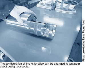
Partners at Florida International University conducted early bench-scale work to evaluate and document glass flow mechanics. Armed with this information and new pour spout designs supplied by DWPF, TFA worked with Clemson University to design and install a DWPF prototypic pour spout with the dual knife-edge configuration in November 1998. Then, in June 1999, a demonstration of the DWPF replacement melter knife edge was completed in the large stirred melter at Clemson University’s Environmental Technology Laboratory. Modifications to the superheater pour valve were successful in reducing hydraulic resistance, while joule heating in the main pot and glass flow through a prototypic pour spout were demonstrated. Continuing TFA and university efforts on melter pour spout improvements will increase efficiency during vitrification operations, saving both time and money for treatment and disposal of high-level waste. TFA provided a prototypic test unit to validate significant design improvements prior to radioactive operation in DWPF. Design recommendations for the new spout will be completed in FY00. Tank closure
The sampling end effector, developed at INEEL, contains a light source, camera (with 0- to 50-ft viewing range), and a radiation detector (with 0–1000 rad/h range). A 2-inch-diameter capture tube can be immersed in up to 16 inches of liquid or soft slurry waste to pull up to 800 cubic centimeters of sample into the evacuated sample chamber. The Light Duty Utility Arm (LDUA) was used to deploy the Heel Sampling End Effector into tanks WM-188 and WM-182 in February and November 1999, respectively. Heel samples were collected from various locations in the tanks and sent to the site’s Remote Analytical Laboratory for analysis. Solid and liquid phases of each heel sample underwent analysis for 29 elements, 18 radionuclides, and 13 organic compounds and were screened for an additional 75 compounds. Data from the heel samples will be analyzed to confirm the historical data presently used to estimate the chemical and corrosive characteristics of the tank heel and to support development of a grout formulation for eventual closure of tanks at the Idaho Nuclear Technology Engineering Center. The sample data will also help define requirements for further waste retrieval efforts, if necessary. For additional information on solutions developed through TFA, see the TFA Web site at http://www.pnl.gov/tfa. |

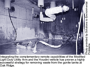 The major components
of the Gunite Tank Cleaning System include a Modified Light Duty Utility Arm (MLDUA), a
Confined Sluicing End Effector, and a Houdini vehicle. The sluicing end effector
  Pulsed-Air Mixer
 Melter knife edge
demonstrations
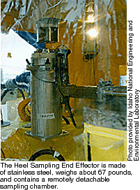 Heel Sampling End Effector