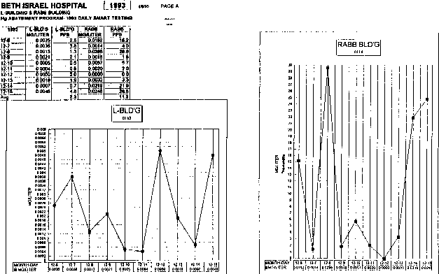
Figure 7.1 Beth Israel Hospital Effluent SMART Testing Result 1993 (No Powerwashing)
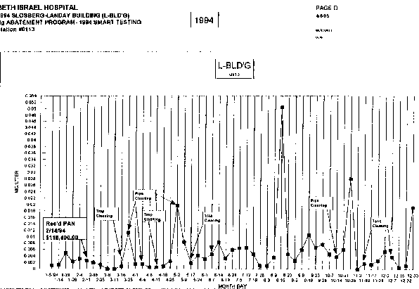
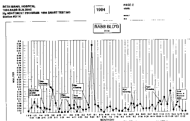
The powerwashing procedure is a recommended way to provide a scouring effect on the accumulated biomass that has adhered to plumbing and piping infrastructure. Powerwashing is an effective, but not permanent, method for removing biomass and preventing biosolids from appearing in the effluent discharges. Figures 7.1 through 7.3 display powerwash pipe cleaning events with associated compliance sampling results from Beth Israel Hospital's discharges from December 1993 to December 1994. The figures show that, in late 1993, effluent mercury concentrations were persistently high but, in 1995, effluent mercury concentrations appear to stabilize after pipe cleaning events. As mentioned in the Problem Overview, the biomass within an institution's conveyance piping may contain concentrations of mercury in the 1,000 part per million range. Several institutions have verified the presence of mercury in the biomass through pilot testing and pipe cleaning protocols. Figure 7.4 is a spreadsheet with some of the initial data determining the presents of mercury in the biomass. This data was generated from pilot testing performed by Beth Israel Hospital showing the relationship between particulate and dissolved mercury after powerwashing.
A typical high pressure/low volume powerwasher pushes water through a nozzle that is designed to remove biomass and grease buildup with a strong scouring action while flushing the debris down the line as the hose and nozzle are fed along the conveyance piping. The more accessible the piping structure is (via cleanouts and access ports), the more successful the power washing effort will be.
Conveyance piping accessibility is essential for successful powerwashing. The following techniques are most efficient when performed on glass piping. The techniques mentioned, hereinafter, will require some modification when cleaning thermo-plastics piping. Powerwashing activities are usually, at a minimum, a two (2) person operation; an operator of the powerwasher and an observer of the nozzle and hose as it moves through the conveyance piping.
The operator begins feeding the 80 to 100 feet of hose with the powerwashing nozzle attached, while the observer, with a two way radio in full communication with the operator, watches the hose and nozzle for potential obstructions and other problems. Typical obstructions include: tees, reducers, p-traps, drum traps and valves. Beth Israel Hospital has determined that successful powerwashing occurred when cleaning operations began at the collection or treatment tanks in the lower

Figure 7.1 Beth Israel Hospital Effluent SMART Testing Result
1993 (No Powerwashing)

Figure 7.2 Beth Israel Hospital Effluent SMART Testing Result
1994 (Powerwashing - L-BLD'G 0113)

Figure 7.3 Beth Israel Hospital Effluent SMART Testing Result
1994 (Powerwashing - RABB BLD'G 0114)
| SLOSBERG LANDAY BUILDING | DANA | RABB | Research North | |||||||||
| Date | Status | #2 RED STACK | #4 ORANGE STACK | #1 GREEN STACK | #3 BLUE STACK | Neut. Tank Sludge | RB-36-1 | RB-36-2 | Main |
3 East |
3 West | |
| 3/16/94 | Before Cleaning | 0.0162 | 1.3300 | 0.1150 | 2.9000 | |||||||
| 3/25/94 | After Trap Cleaning | 0.0097 | 0.0439 | 0.0019 | 2.0400 | |||||||
| 4/11/94 | After Power Washing | 0.1560 | ||||||||||
| 4/21/94 | After Time to Settle | 0.0565 | 0.4936 | 0.0537 | 0.0063 | 0.0197 | ||||||
| 5/6/94 | After 2nd Power Washing | 4.01 | ||||||||||
| 5/9/94 | After Time to Settle | 5.04 | ||||||||||
| 6/10/94 | 0.259 | 3.83 | 0.0166 | <North | ||||||||
| 0.327 | <South | |||||||||||
| 7/28/94 | 19.1 | 0.203 | 1.8 | 0.0048 | 0.0218 | |||||||
| 8/24/94 | 9.23 | 0.0642 | 0.305 | 0.0059 | ||||||||
| 9/1/94 | ND | 0.0002 | ND | |||||||||
| 9/29/94 | Total | 0.0022 | 0.0030 | 0.0046 | 0.0027 | 7.1200 | ||||||
| Dissolved | 0.0005 | 0.0006 | ND | 0.0070 | 0.0088 | |||||||
| Particulate | 0.0017 | 0.0024 | 0.0046 | 0.0199 | 7.1112 | |||||||
| % Dissolved | 22.73% | 20.00% | 0.00% | 26.02% | 0.12% | |||||||
| % Particulate | 77.27% | 80.00% | 100.00% | 73.98% | 99.88% | |||||||
floors, and worked backwards, towards the sources, in a reverse flow direction. This technique is preferred because the nozzle is designed with a reverse flow head configuration that literally "pulls" the hose away from the powerwasher operator and towards the sources while flushing biomass and debris down the line and on to the collection point. Another benefit to washing in a reverse flow direction is that most plumbing fittings have smooth swings in the reverse direction and this seems to help reduce the number of obstruction interferences. Though this is the preferred method, trial and error may have to be applied due to the complexities of the piping infrastructure. For immediate success, select straight sections that are observed to contain biomass. In other locations, piping may have to be removed or modified in order to reach areas of concern. Powerwashing on thermo-plastic piping will require a lot more trail and error and it may be necessary to remove piping sections to verify cleaning effectiveness. Note thqat the installation of a sight glass may help to minimize the amount of sections to be removed. Sometimes it will be difficult or impossible to feed the hose and nozzle in reverse direction. In these cases, an alternative method would be to to start at the sources (sink traps or floor drains) and work in the direction of flow. This technique, however, is less desirable because the nozzle head will not be flushing debris as it moves along the piping. It may be necessary, in this instance, to apply additional water to aid the flushing process by turning on an adjacent sink that is tied into the same conveyance line.
The following are some precautions that should be considered prior to implementing powerwashing procedures: 1) It should be assumed that all materials contained within the conveyance piping are hazardous, and, prior to beginning powerwashing activities, approval by the institution's Health and Safety Officer should be obtained to help ensure that proper personnel protective equipment is being used; 2) Powerwashing is not a delicate operation and sometimes conveyance fittings and piping, especially with glass fittings, can be cracked or broken. It is necessary to inspect the entire run prior to powerwashing, and identify any potential obstructions, so that if a fitting is broken, a replacement fitting is immediately available for instillation; and, 3) Conveyance piping that contains large amounts of biomass may, once dislodged, begin to collect and clog downstream conveyance piping sections. If the piping begins to clog and eventually prevents flow due to accumulation of this dislodged biomass, there will be a significant potential for wastewater backing up in the plumbing system and causing flooding at lower elevation locations.
All powerwashing wastewater that contains removed biomass should be assumed to contain levels of mercury above the MWRA's allowable discharge limit of one (1) ppb, and should be collected for off-site disposal. Refer to Section 10.0 for recommended mercury waste disposal procedures.
The collection of the powerwash wastewater will be a difficult task but, since powerwashing will usually occur during non-operating hours, the systems, hopefully, will be virtually drained. Once flow has stopped, the treatment tank can then be emptied and used as a powerwashing wastewater collection vessel. After powerwashing is completed or the treatment tanks are getting full, transfer all collected wastewater into storage containers. This is only one recommended method for collecting wastewater and, there are other collection and pumping methods that can be used on a case-by-case basis. However accomplished, it is very important that this wastewater is collected and not be allowed to be discharged.
A typical piece of equipment that has been used by Beth Israel Hospital in the power washing of their infrastructure piping is the KJ-1250 Water Jetter (See Appendix C). This unit is a compact, portable machine designed to clear biomass, grease and sludges out of 1-1/4" to 4" diameter drain lines. It can be either hand carried or combined with a two wheel cart and hose reel for easy transport.
The equipment specifications are as follows:
| Line capacity | 1-1/4" to 4" drain lines through 150 feet |
| Motor | 115V/60 Hz TEFC or 240 V/50Hz |
| Rating | 11/2 Hp @ 1725 RPM |
| Pump> | Duplex Plunger |
| Pressure | 1500 PSI |
| Flow Rate | 1.5 GPM |
| Weight | 70 lbs |
The powerwasher mentioned in this section does not allow for the addition of chemistry as powerwashing is performed. This limitation is do to the long lengths of hose and the design of the equipment. A powerwasher with the capabilities of adding chemicals and high pressure water simultaneously could further enhance the effectiveness of the washing. Further investigation of other powerwashing equipment that aspirate chemical during powerwashing are currently available or facilities should work with vendors of existing equipment to see if their units could be modified to incorporate this feature.
The basic unit can be used with water only to provide a scouring agitation. However, it is recommended that a bleach solution be added to the length of piping at the source, if possible, to help disinfect that section prior to powerwashing. Before adding bleach or an other disinfectant chemical, it should all be analyzed to ensure that it is mercury free or of a "low" mercury content. The MWRA/MASCO Hospital Work Group, Operations Subcommittee has identified that several chemicals and reagents, including many disinfecting products that contain bleach, also contain considerable amounts of mercury
The addition of surfactants, dispersants, caustics and/or wetting agents could potentially increase the powerwashing effectiveness. To date, there have been eight cleaning chemicals and combinations of these chemicals investigated through a pipe cleaning protocol effort that was developed for Medical Academic and Scientific Community Organization, Inc. (MASCO). The results of this protocol are presented in Section 8.0 of this Guidebook.
| Previous | Contents | Next |