|
|
Cleaner Production Demonstration Project at Holden's Engine Company, Port Melbourne, Victoria
|
Table of Contents
APPENDIX A
CURRENT OPERATION OF THE HEC TRADE WASTE TREATMENT PLANT (TWTP)
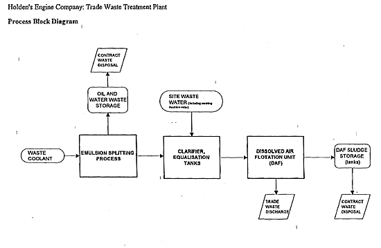
 As shown in following figure, the TWTP is separated into two functional
areas, coolant emulsion-splitting and wastewater treatment. The
coolant emulsion-splitting process takes oil-contaminated wastewater,
such as spent coolant, metal working fluids and lubricant-contaminated
water into aerated storage tanks prior to further treatment to
separate the emulsified oil and grease component (emulsion splitting).
This is achieved by dosing the coolant with a proprietary brand
of polymer solution and ferric chloride and controlling the pH
with caustic soda and hydrochloric acid. The specific batch dosage
of chemicals is determined by the in-house laboratory. Occasionally,
brine dosing is utilised to split the emulsion. Recovered oil
and grease waste (containing up to 50% water) which is separated
at the emulsion splitting stage is transferred to an 18,000 litre
waste oil tank, which is periodically pumped out for disposal
by a sludge removal contractor.
As shown in following figure, the TWTP is separated into two functional
areas, coolant emulsion-splitting and wastewater treatment. The
coolant emulsion-splitting process takes oil-contaminated wastewater,
such as spent coolant, metal working fluids and lubricant-contaminated
water into aerated storage tanks prior to further treatment to
separate the emulsified oil and grease component (emulsion splitting).
This is achieved by dosing the coolant with a proprietary brand
of polymer solution and ferric chloride and controlling the pH
with caustic soda and hydrochloric acid. The specific batch dosage
of chemicals is determined by the in-house laboratory. Occasionally,
brine dosing is utilised to split the emulsion. Recovered oil
and grease waste (containing up to 50% water) which is separated
at the emulsion splitting stage is transferred to an 18,000 litre
waste oil tank, which is periodically pumped out for disposal
by a sludge removal contractor.
Wastewater from the emulsion splitting stage is then mixed with
other process wastewater at the wastewater treatment plant.
The wastewater treatment stage of the TWTP primarily takes washing-machine
wastewater from the plants and treated wastewater from the emulsion-splitting
stage where it is aerated in two balance tanks and held until
batch treatment is to be commenced. Batch treatment begins in
the flocculating tank where ferric chloride is added to aid in
coagulation. pH adjustment also occurs in this tank. Flocs are
not settled out of the wastewater at this stage, with effluent
flowing directly to the flash mixing tank where dosing with polyelectrolyte
occurs to enhance floc development.
Treatment in the Dissolved Air Flotation unit (DAF) follows, with
the DAF unit being entirely responsible for the removal of suspended
solids from the wastewater stream. Effluent from the DAF is disposed
to trade waste with the sludge being transferred to a series of
holding tanks. Supernatant liquid from the holding tanks is returned
to the balance tanks for re-treatment.
The process is operator dependant, to enable staff to monitor
operating parameters such as ammonia production and sludge accumulation.
Fully automated control at the waste treatment operation is utilised
only when there is a personnel shortage.
APPENDIX B
LIST OF COOLANT SYSTEMS AS AT 1 JULY 1995
| Plant Number
| Coolant System Number
| System Capacity (Litres)
|
| "Small Systems"
| | |
| 4 |
2A | 15000
|
| M05 -25-121
M05-25-122
| 1900 |
| M45-01-866
| 3000 |
| M05-43-222
| 3000 |
| M45 -01-865
| 3000 |
| 10 |
M05-10-70 |
8000 |
| 16 |
9 | 9000
|
| 10A
| 16000
|
| 13
| 40000
|
| 18
| 20000
|
| "Large Systems"
| | |
| 4 |
1 | 80000
|
| 2
| 45000
|
| 17
| 15000
|
| 10 |
3 | 80000
|
| 4
| 60000
|
| 16 |
15 | 36000
|
| 16
| 88000
|
| 16 |
M05-43-143
| 15,000
|
TABLE OF CONTENTS