Similar to the situation when designing recovery for VOC aqueous wastes, it is necessary to determine equilibrium data for the technologies previously described in order to design a recovery system for gaseous VOC wastes. Accurate experimental results provide the most reliable source for equilibrium data. If not available, empirical correlations for predicting equilibrium data may be invoked. These correlations are particularly useful at the conceptual-design stage. Several literature sources provide compilations of equilibrium data and correlations. For instance, Yaws et al. (1995) and Valenzuela (1989) have provided equilibrium data for activated carbon adsorption. Condensation equilibrium data needed for the recovery of VOC's from gaseous emissions is twofold. First, vapor pressure data for the VOC is required. Examples of this data can be found in Yaws (1994) and Reid (1977). Second, thermodynamic data for the refrigerant/coolants considered for the condensation process are also required for the design task. Several refrigerants are available for VOC condensation (Sibley, 1983). Typical inorganic refrigerants commonly used are liquid ammonia, liquid sulfur dioxide, and liquid nitrogen. In addition, organic refrigerants referred to as CFC's (chlorofluorocarbons) are also used for industrial refrigeration processes. However, manufacturers of CFC's must cease production by year end 1995 because of the ozone depletion potential of these compounds. Substitute refrigerants in the form of HCFC's (hydrochlorofluorocarbons) and HFC's (hydrofluorocarbons) are now being produced since they pose little to no ozone depletion potential (Brandt, 1992; Moore, 1992).
Brandt, E., The Eradication of CFC's, Chem. Engr. 99: 63, 1992.
Moore, T., Refrigerants for an Ozone-Safe World, EPRI J., 17: 22, 1992.
Reid, R. C., The Properties of Gases and Liquids, McGraw-Hill, New York, 1977.
Sibley, H. W., Selecting Refrigerants for Process Systems, Chem. Engr., 90: 71, 1983.
U. S. EPA, Control Technologies for Hazardous Air Pollutants, EPA/625/6-91/014, 4.55-4.64, 1991.
Valenzuela, D. P. and A. Myers, Adsorption Equilibrium Data Handbook, Prentice-Hall Inc., Englewood Cliffs, NJ, 1989.
Yaws, C. L., Thermodynamic and Physical Property Data, Gulf Publishing Company, Houston, TX, 1992.
Yaws, C. L., Handbook of Vapor Pressure, Vol. 1, Gulf Pub. Co., Houston, P. 343, 1989.
Yaws, C. L., Li Bu and Sachin Nijhawan, Adsorption Capacity Data for 283 Organic Compounds, Envir. Engr. World, 1(3), 16-20, 1995.
Cahpters three and seven have presented the background information needed to design a separation system for VOC gaseous wastes. This chapter will provide the designer with a systematic approach for identifying the VOC separation system possessing the minimum total annualized cost to the company.
Several key definitions definitions are needed prior to discussing the design strategy. These are summarized below:
Mass Exchanger - Any countercurrent direct-contact mass-transfer operation that uses a mass-separating agent (MSA) to accomplish the transfer of a certain species (VOC in this case) to the mass separating agent. Examples of mass exchangers are absorption columns, carbon adsorbers, stripping columns, extraction columns and ion exchange columns. Examples of MSA's for VOC separation are activated carbon when employing adsorption and a liquid absorbent (typically an oil) when using absorption.
Heat-Induced Separator - Any indirect-contact unit which employs an energy-separating agent (ESA) for the separation of certain species via phase change. Examples of heat-induced separators are condensers, evaporators, crystallizers and dryers. Examples of ESA's for VOC separation are refrigents and coolants.
Mass Exchange Networks - System of one or more mass exchangers.
Heat-Induced Separation Networks - System of one or more heat-induced separators.
Energy-Induced Separation Networks - System of one or more heat-induced separators along with pressurization and depressurization devices, such as compresors and turbines.
In order to identify the cost-effective separation system for VOC gaseous wastes, the designer must initially classify the technologies that can be used for the separation task. Two of the separation processes, liquid absorption and carbon adsorption, involve direct contact mass transfer; therefore, these processes can be classified within the category of mass exchange networks. Condensation and condensation-hybrid processes involve indirect cooling of the VOC gaseous stream and are classified within the category of energy induced separation networks. Finally, membrane-hybrid processes are generically classified within the category of membrane-hybrid networks. Since the thermodynamic principles governing these three types of process networks are fundamentally different, the optimal design of processes within these classifications have been solved independently of one another. This chapter will briefly outline the Design of Mass Exchange Networks, theDesign of Energy Induced Separation Networks and the Design of Membrane-Hybrid Networks as appied to the separation of VOC gaseous wastes.
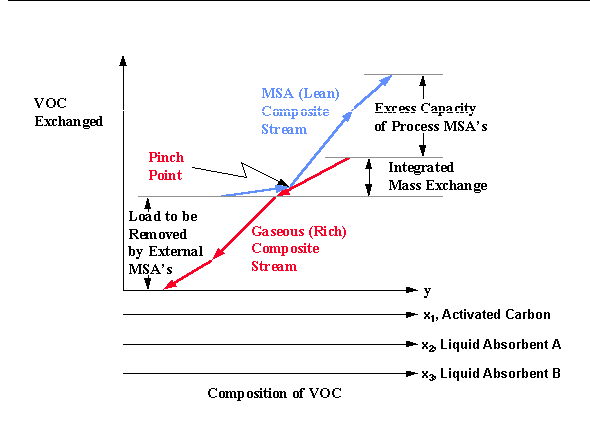
The design of mass exchange networks, using the mass exchange pinch diagram (El-Halwagi and Manousiouthakis, 1989), has been previously described in the chapter covering the Design of Separation Systems for Aqueous Wastes. This design approach can be extended directly to the design of cost effective liquid absorption and carbon adsorption networks. A sample pinch digram for this design approach is shown below. Two liquid absorbents, either internal process streams, are illustrated on Figure 8.1; however, any number of liquid absorbents, along with activated carbon, can be simultaneously screened for the separation task.

Similar to the case for the design of separation systems for VOC aqueous wastes, the amount of VOC that can be transferred from the aqueous wastes to the process MSA's is represented by the vertical overlap between the composite streams and is referred to as the "integrated mass exchange." The vertical distance of the MSA (lean) composite stream which lies above the upper end of the gaseous (rich) composite stream is referred to as "excess process MSA's." It corresponds to that capacity of the process MSA's to remove pollutants which cannot be used because of thermodynamic infeasibility. According to the designer's preference or to the specific circumstances of the process such excess can be eliminated from service by lowering the flowrate and/or the outlet composition of one or more of the process MSA's. Finally, the vertical distance of the gaseous composite stream which lies below the lower end of the MSA composite stream corresponds to the mass of pollutant to be removed by external MSA's. External MSA's can then be screened based on the cost of each external MSA per unit mass of VOC removed.
Design of Energy Induced Separation Networks for Gaseous VOC Separations
A graphical technique for designing a cost-effective VOC condensation system for gaseous wastes has been developed by Richburg and El-Halwagi, 1994. This technique is based on the general system configuration shown in Figure 8.2.
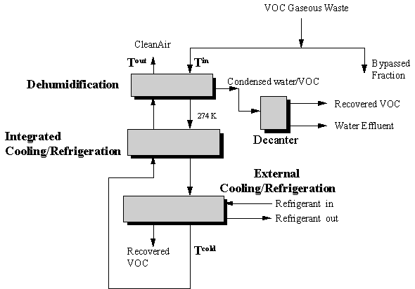
For the network shown, it is desired to determine the flowrate and type of refrigerant needed to condense a prespecified quantity of VOC from the gaseous waste stream(s). The operating temperature and cost ($/kJ) are known for each refrigerant considered for the separation task.
Initially, the design problem is converted from a separation task to a heat transfer duty. In general, it is necessary for the designer to predetermine the temperature, denoted T* in the previous figure, that the waste stream must be cooled to in order to satisfy the desired removal rate. This temperature can be determined based on the stream total pressure and the stream vapor pressure at the temperature that the stream is cooled to. After the stream temperature is determined, a minimum temperature driving force is preset by the designer for each exchanger (denoted in grey in the previous figure). Next, a pinch diagram (Linnhoff and Hindmarsh, 1982) is established by plotting enthalpy versus temperature for the VOC gaseous waste (shown as the T scale) and for the recycled cold portion of this gas (shown as the t scale). An example pinch diagram for VOC condensation is shown on Figure 8.3.
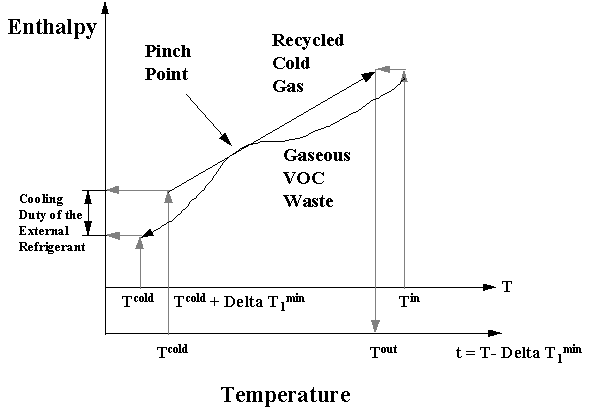
The recycled cold gas stream is moved vertically until it touches the gaseous VOC stream and the point at which the streams contact is called the pinch point and represents a thermodynamic bottleneck for the design. Since these streams can not cross, moving the recycled cold gas stream until the pinch point is established allows the designer to determine the cooling duty required by an external refrigerant as indicated on the y axis. It also allows the designer to determine the oulet gas temperature from the network, which has been denoted Tout.
The next step in the design process is to select the external refrigerant to be used. This is accomplished by selecting the refrigerant operating below T* that possesses the minimum operating cost ($/kJ). Finally, tradeoffs between fixed costs and operating costs are made by calculating the overall network cost (operating plus capital cost) for several values of delta T1min. It has been established that some value of delta T1min represents the most cost-effective design. It is worth pointing out that cost-effective designs involving other process configurations have been developed (El-Halwagi et al., 1994).
Dunn et al., 1995, have extended this graphical technique to include pressurization devices (compressors) and depressurization devices (turbines) for the design of condensation-hybrid separation systems. Pressure is increased to increase VOC recovery efficiency and potentially eliminate cryogenic temperatures and depressurization is incorporated for energy recovery. For this design case the network structure in Figure 8.4 is used.
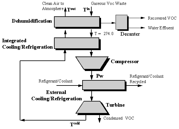
The solution technique is similar to that previously described except that a double iteration process is necessary. For a preselected value of Pw, the pressure of the gas stream exiting the compressor, network costs (operating plus capital) are determined at several values of delta T1min. This procedure is repeated for several values of Pw to determine the value of Pw and T1min which results in the minimum network cost. A flowsheet summarizing this design procedure is shown in Figure 8.5.
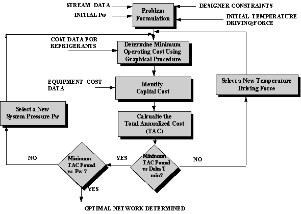
A more robust design technique for Condensation-Hybrid Separation Systems using the State-Space method previously mentioned (Design of Separation Systems for Aqueous Wastes) has been developed by Dunn et al., 1995.
Two design approaches have been recently developed for membrane-hybrid systems (Crabtree et al., 1995). The first approach developed uses a pre-defined network structure combined with a mathematical program to determine system parameters (pressures, flowrates, etc.) that represent the minimum operating and capital cost for this network. The second approach is more mathematically rigorous and utilizes the state-space methodology. This approach does not require a pre-defined network structure and results in the identification of the network configuration, and operating parameters, that possesses a minimum total annualized cost.
A polyvinyl chloride (PVC) manufacturing plant has a gaseous emission stream exiting at a flowrate of 0.03 kmol/s and a vinyl chloride mole fraction of 0.02 (U.S. EPA, 1981). It is desired to design a network of energy-induced separation units that will condense vinyl chloride vapors such that 90% of the vinyl chloride in the emission stream is recovered. Two refrigerants are considered for the VOC condensation task, liquid ammonia and liquid nitrogen. All necessary economic and thermodynamic data for this case study are given in Attachment 8-I.
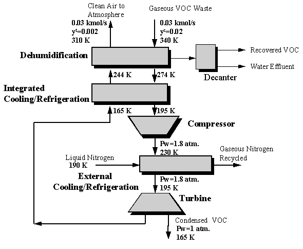
The shortcut graphical procedure was used to generate a solution whose total annualized cost was found to be $101,300. The optimal pressure, Pw, for compression was found to be 1.8 atmospheres. The final network operating conditions are shown in the Figure 8.6 below.
Crabtree, E., R. F. Dunn and M. M. El-Halwagi, Synthesis of Membrane/Condensation Hybrid Systems for Solvent Recovery, 1995 North American Membrane Society Annual Meeting, Portland, 1995.
Dunn, R. F., M. Zhu, B. K. Srinivas, and Mahmoud El-Halwagi, Optimal Design of Energy-Induced Separation Networks for VOC Recovery, AIChE J. Symp. Series, 90(103), 74-85, 1995.
El-Halwagi, M. M., B. K. Srinivas and R. F. Dunn, Synthesis of Optimal Heat-Induced Separation Networks. Chem. Eng. Sci., 50(1), 81-97, 1995.
El-Halwagi, M. M. and V. Manousiouthakis, Synthesis of Mass-Exchange Networks, AIChE J., 35(8), 1233-1244, 1989.
Linnhoff, B. and E. Hindmarsh, The Pinch Design Method for Heat Exchange Networks, Chem. Eng. Sci., 38, 745-763, 1983.
Richburg, A. and M. M. El-Halwagi, 1994, A Graphical Approach to the Optimal Design of Heat-Induced Separation Networks for VOC Recovery, Foundations in Computer-Aided Process Design, Volume 91, 256-259, 1995.
Overall Gas Flow Rate = 0.03 kmol/s
Ts=340K
ys=0.02 mole fraction
Desire to recovery 90 mole % of the VOC (yt=0.002)
Cpair = 29 kJ/kmol K
=24,000 kJ/kmol
k = 1.4 (dimensionless)
Gas-gas overall heat transfer coefficient (Heat Exchangers 2 and 3)=0.05 kW/m2K
VOC-condensation overall heat transfer coefficient (Heat Exchanger 1)=0.1 kW/m2K
Cost of Refrigerants (Operating + Fixed Cost)
CostNH3 = $ 3/106 kJ
TNH3 = 254 K
CostN2 = $ 5/106 kJ
TN2 = 190 K
Fixed Cost of Compressors and Turbines:
where C is the cost in $ and W is the compressor or turbine work in hp
Electricity Cost = $ 0.04/kWh
Cost of Heat Exchanger 1 = 9500.Area0.6 ,where area is in m2
Cost of Heat Exchangers 2 and 3 = 1500.Area0.6, where area is in m2
Installed cost of heat exchangers, turbines and compressors = 3 times the equipment cost.
Equipment cost was annualized over a 5 year life.
In this document, we have provided systematic methods for cost-effective waste management of VOC's, primarily by using recycle/reuse separation systems. In this chapter, we broaden the scope of discussion and introduce the new design philosophy of Total Waste Management "TWM". While the main focus of waste management is to reduce the negative environmental impact of a process, TWM addresses a more general concept of waste. Waste refers to any wasteful activity or waste of resources in the process which restrict the company from attaining its optimal performance. In this context, examples of waste include:
This conceptualization of waste reconciles the various process objectives (productivity, yield, pollution prevention, energy efficiency, etc.) At first glance, it may appear that it is an overwhelming task to simultaneously address these issues. The good news is that over the past decade several breakthroughs have been accomplished in the area of process integration. These accomplishments enable the designer to determine best performance targets for a process without undertaking detailed analyses. These performance targets include maximum energy integration (Linnhoff and Hindmarsh, 1983), maximum mass integration, (El-Halwagi, 1995; Stanley and El-Halwagi, 1995, Dunn and El-Halwagi, 1993; El-Halwagi and Srinivas, 1992; El-Halwagi and Manousiouthakis, 1989, 1990a, 1990b) and combined separation and energy integration (Dunn et al., 1995; Crabtree et al., 1995; El-Halwagi et al., 1995; Srinivas and El-Halwagi, 1993, 1994; Dunn and El-Halwagi, 1994a, 1994b; El-Halwagi, 1992). Details of how these tools can be employed to develop a TWM is beyond the scope of this document. Based on the rate of recent works in this area, we believe that this methodology will come of age within the next few years.
Crabtree, E., R. F. Dunn and M. M. El-Halwagi, Synthesis of Membrane/Condensation Hybrid Systems for Solvent Recovery, 1995 North American Membrane Society Annual Meeting, Portland, 1995.
Dunn, R. F., M. Zhu, B. K. Srinivas, and M. M. El-Halwagi, Optimal Design of Energy-Induced Separation Networks for VOC Recovery, AIChE J. Symp. Series, 90(103), 74-85, 1995.
Dunn, R. F. and M. M. El-Halwagi, Optimal Recycle/Reuse Policies for Minimizing the Wastes of Pulp and Paper Plants, J. Envir. Sci. & Health, A28(1), 217-234, 1993.
El-Halwagi, M. M., Introduction to Numerical Approaches to Pollution Prevention, Waste Minimization through Process Design, McGraw-Hill, Inc., 199-208, 1995.
El-Halwagi, M. M., B. K. Srinivas and R. F. Dunn, Synthesis of Optimal Heat-Induced Separation Networks, Chem. Eng. Sci., 50(1), 81-97, 1995.
El-Halwagi, M. M., Synthesis of Optimal Reverse-Osmosis Networks for Waste Reduction, AIChE J., 38(8), 1185-1198, 1992.
El-Halwagi, M. M. and B. K. Srinivas, Synthesis of Reactive Mass-Exchange Networks, Chem. Eng. Sci., 47(8), 2113-2119, 1992.
El-Halwagi, M. M. and V. Manousiouthakis, Automatic Synthesis of Mass Exchange Networks with Single-Component Targets, Chem. Eng. Sci., 45(9), 2813-2831, 1990a.
El-Halwagi, M. M. and V. Manousiouthakis, Simultaneous Synthesis of Mass Exchange and Regeneration Networks, AIChE J., 36(8), 1209-1219, 1990b.
El-Halwagi, M. M. and V. Manousiouthakis, Synthesis of Mass Exchange Networks, AIChE J., 35(8), 1233-1244, 1989.
Linnhoff, B. and E. Hindmarsh, The Pinch Design Method for Heat Exchange Networks, Chem. Eng. Sci., 38, 745-763, 1983.
Srinivas B. K. and M. M. El-Halwagi, Synthesis of Combined Heat and Reactive Mass-Exchange Networks, Chem. Eng. Sci., 49(13), 2059-2074, 1994.
Srinivas, B. K. and M. M. El-Halwagi, Optimal Design of Pervaporation Systems for Waste Reduction, Comp. Chem. Eng., 17(10), 957-970, 1993.
Stanley, C. and M. M. El-Halwagi, Synthesis of Mass-Exchange Networks Using Linear Programming Techniques, Waste Minimization through Process Design, McGraw-Hill, Inc., 209-224, 1995.
[The following terms may be found by searching this document using the search tool built into your Netscape or Microsoft browser.]
|
|